Elevating conveyer

A technology for conveyors and conveyor lines, which is applied in the direction of conveyors, conveyor objects, transportation and packaging, etc. It can solve the problems that the conveyor lines are not in the same plane and low efficiency, and achieve the effect of uniform force and guaranteed transmission efficiency

Inactive Publication Date: 2017-06-13
WUXI MINGZHU TURBOCHARGER MFG
View PDF5 Cites 3 Cited by
  • Summary
  • Abstract
  • Description
  • Claims
  • Application Information

AI Technical Summary

Problems solved by technology

[0002] Pallets are common parts used to place items. Pallets include wooden pallets and metal pallets. Metal pallets need to be transported and discharged after being processed. Due to the needs of the assembly line and the setting of the station, there will be problems in the subsequent discharge process. The conveyor line is not on the same plane. The existing method is generally to manually move it from the previous conveyor line to another conveyor line with a higher position, which is less efficient

Method used


Image

  • Elevating conveyer
  • Elevating conveyer

Examples


Embodiment Construction

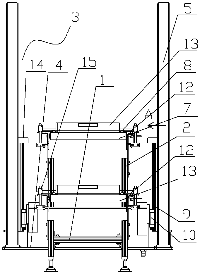
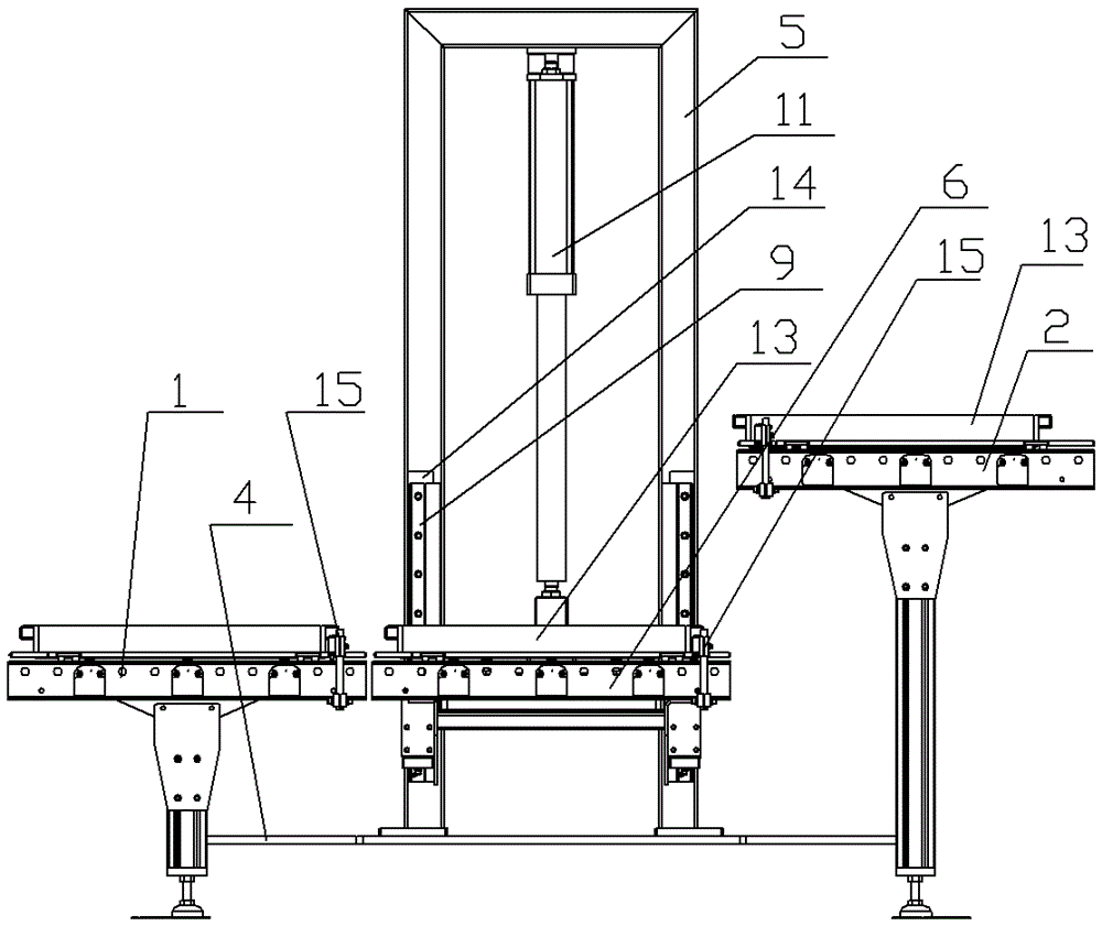
[0013] See figure 1 , figure 2 As shown, a lifting conveyor includes a first conveying line 1 and a second conveying line 2, the height of the second conveying line 2 is higher than that of the first conveying line 1, between the first conveying line 1 and the second conveying line 2 A lifting mechanism 3 is provided, and the lifting mechanism 3 includes a bottom plate 4. The front and rear ends of the bottom plate 4 are fixedly connected to the first conveying line 1 and the second conveying line 2. The left and right sides of the bottom plate 4 are respectively equipped with inverted U-shaped brackets 5, two inverted U Lifting brackets 6 are arranged between the shaped brackets 5, and a plurality of electric rollers 7 are installed on the lifting brackets 6. The left and right sides of the electric rollers 7 are respectively equipped with limit stop rods 8, and the two vertical bars of the two inverted U-shaped brackets 5 The inner side is respectively equipped with linear...


PUM


Abstract

The invention relates to the technical field of pallet conveying equipment, in particular to a lifting conveyor, which can conveniently realize the automatic lifting of pallets, is stable and reliable, and ensures conveying efficiency. It includes a first conveying line and a second conveying line, and the second conveying line The height is higher than the first conveyor line, and a lifting mechanism is arranged between the first conveyor line and the second conveyor line. The lifting mechanism includes a bottom plate. An inverted U-shaped bracket is installed, and a lifting bracket is arranged between the two inverted U-shaped brackets. Multiple electric rollers are installed on the lifting bracket. The inner sides of the two vertical rods are respectively equipped with linear guide rails, and the left and right sides of the lifting bracket are respectively connected to the linear guide rails through sliders. The two sliders on the same side are connected through an intermediate connecting rod, and the intermediate connecting rod is connected to the piston rod of the longitudinal drive cylinder. .

Description

technical field [0001] The invention relates to the technical field of pallet conveying equipment, in particular to a lifting conveyor. Background technique [0002] Pallets are common parts used to place items. Pallets include wooden pallets and metal pallets. Metal pallets need to be transported and discharged after being processed. Due to the needs of the assembly line and the setting of the station, there will be problems in the subsequent discharge process. The conveying line is not on the same plane. The existing method is generally to manually move it from the previous conveying line to another conveying line with a higher position, which is less efficient. Contents of the invention [0003] In order to solve the above problems, the present invention provides a lifting conveyor, which can conveniently realize the automatic lifting of the tray, is stable and reliable, and ensures the conveying efficiency. [0004] Its technical solution is as follows: a lifting conv...

Claims


Application Information

Patent Timeline
IPC IPC(8): B65G47/57
CPCB65G47/57B65G2201/0258
Inventor 尤梦蝶
Owner WUXI MINGZHU TURBOCHARGER MFG
Why Eureka
Try Eureka