
Automatic speed-reduction rewinder

A rewinding machine, automatic technology, applied in the field of toilet paper production, can solve the problems of speeding up the roll paper, toilet paper cracking, paper breaking, etc.

Inactive Publication Date: 2017-06-13
重庆一锄科技有限公司
View PDF5 Cites 0 Cited by
  • Summary
  • Abstract
  • Description
  • Claims
  • Application Information

AI Technical Summary

Problems solved by technology

[0003] When rewinding the toilet paper, both the large paper roll and the rewinding paper roll rotate, the large paper roll releases the paper at a constant speed, and the rewinding paper roll rewinds at a constant speed. However, as the toilet paper on the rewinding paper roll As the thickness gradually increases, the cutting radius of the rewinding paper roll increases gradually, and the linear speed on its surface gradually increases. Therefore, after rewinding for a certain period of time, although the rotation speed of the center of the rewinding paper roll remains unchanged, the speed of the rewinding paper gradually increases. , so that the toilet paper between the rewinding paper roll and the large paper roll produces a certain tension. When the tension gradually increases, it will cause the toilet paper to crack and cause paper breaks

Method used


Image

  • Automatic speed-reduction rewinder
  • Automatic speed-reduction rewinder

Examples


Embodiment Construction

[0014] The present invention will be described in further detail below by means of specific embodiments:

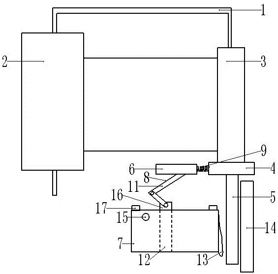
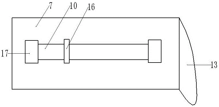
[0015] The reference signs in the accompanying drawings of the specification include: frame 1, large roll paper roll 2, rewind paper roll 3, turntable 4, turning rod 5, push block 6, gas filling box 7, L-shaped connecting rod 8, spring 9 , chute 10, pole 11, piston 12, elastic air bag 13, baffle plate 14, vent hole 15, thin handle 16, limit block 17.

[0016] The embodiment is basically as figure 1 and figure 2 Shown: automatic speed-reducing rewinding machine, including frame 1, large roll paper roll 2, rewind paper roll 3 and speed reduction mechanism, large roll paper roll 2 is connected to the left end of frame 1 in rotation, and rewind paper roll 3 Rotationally connected to the right end of the frame 1, the lower end of the rewinding paper roller 3 is welded with a turntable 4, and the lower end of the turntable 4 is welded with a rotating rod 5, and the right sid...


PUM


Abstract

The invention relates to the technical field of toilet paper production, and discloses an automatic speed-reduction rewinder. The automatic speed-reduction rewinder comprises a rack, a large paper winding roll and a paper rewinding roll, wherein the large paper winding roll and the paper rewinding roll are separately connected to two ends of the rack in a rotary manner; one end of the paper rewinding roll is fixedly connected with a rotary disc; the other end of the rotary disc is fixedly connected with a rotary rod; the automatic speed-reduction rewinder further comprises a speed reduction mechanism; the speed-reduction mechanism is arranged between the large paper winding roll and the paper rewinding roll; the speed-reduction mechanism comprises a pushing block and an air-entrapping box; an L-shaped connection rod is arranged between the pushing block and the air-entrapping box; the L-shaped connection rod comprises two branch rods which are hinged to each other; a spring is connected between the pushing block and the rotary disc; two ends of the air-entrapping box are provided with openings; the opening at one end, close to the rotary rod, of the air-entrapping box is provided with an elastic gas bag; a chute is arranged on the top of the air-entrapping box; a piston is arranged in the air-entrapping box, and is in clearance fit with the air-entrapping box; a slender handle is arranged on the piston; and the slender handle is connected into the chute, and is fixedly connected with the L-shaped connection rod. By adopting the automatic speed-reduction rewinder, effective speed reduction of the paper rewinding roll can be realized during paper rewinding.

Description

technical field [0001] The invention relates to the technical field of toilet paper production, in particular to an automatic speed-reducing rewinder. Background technique [0002] Roll paper is an indispensable thing in daily life and has a good cleaning effect. The main raw material of sanitary roll paper is wood, and its production process is to break the wood into pieces, cook it to make it into wood pulp, mix the wood pulp with water and minerals into pulp, and then go through a series of treatments to remove the water in it, and then It is pressed with a roller, then wound onto a large roller, rewound into a small roll, and finally cut into shape. [0003] When rewinding the toilet paper, both the large paper roll and the rewinding paper roll rotate, the large paper roll releases the paper at a constant speed, and the rewinding paper roll rewinds at a constant speed. However, as the toilet paper on the rewinding paper roll As the thickness gradually increases, the cu...

Claims


Application Information

Patent Timeline
IPC IPC(8): B65H18/10B65H23/06
CPCB65H18/10B65H23/063B65H2801/84
Inventor 刘显苹
Owner 重庆一锄科技有限公司
Learn More