
Retractable loose winding drum for testing optical cable

A disc and loose winding technology, which is applied in the direction of optical instrument testing, machine/structural component testing, measuring devices, etc., can solve the problems of uneconomical, deformation damage, manpower and material resources, etc.

Pending Publication Date: 2017-06-13
YANGTZE OPTICAL FIBRE & CABLE (SHANGHAI) CO LTD
View PDF0 Cites 6 Cited by
  • Summary
  • Abstract
  • Description
  • Claims
  • Application Information

AI Technical Summary

Problems solved by technology

It is very difficult to achieve the loose winding form of the optical cable in this traditional way, because the test requires that the diameter of the central tube is greater than 1 meter, the overall volume of the disc is large, and there are many screws, nuts, gaskets, and central tube plates. In the face of another part of the collapse, multiple workers are required to cooperate for one disassembly and assembly, which takes at least an hour; when the temperature cycle test is carried out on the optical cable every day, the workers need to disassemble and assemble the plate many times, which is very time-consuming; Afterwards, it is prone to deformation and damage, and cannot meet the test requirements. It needs to be scrapped and replaced regularly, which is very uneconomical
It is very time-consuming, material-consuming, manpower-intensive and resource-intensive to meet the optical cable testing requirements by disassembling and assembling wooden discs

Method used


Image

  • Retractable loose winding drum for testing optical cable
  • Retractable loose winding drum for testing optical cable
  • Retractable loose winding drum for testing optical cable

Examples


Embodiment Construction

[0036] The present invention will be further described below in conjunction with the accompanying drawings and embodiments.

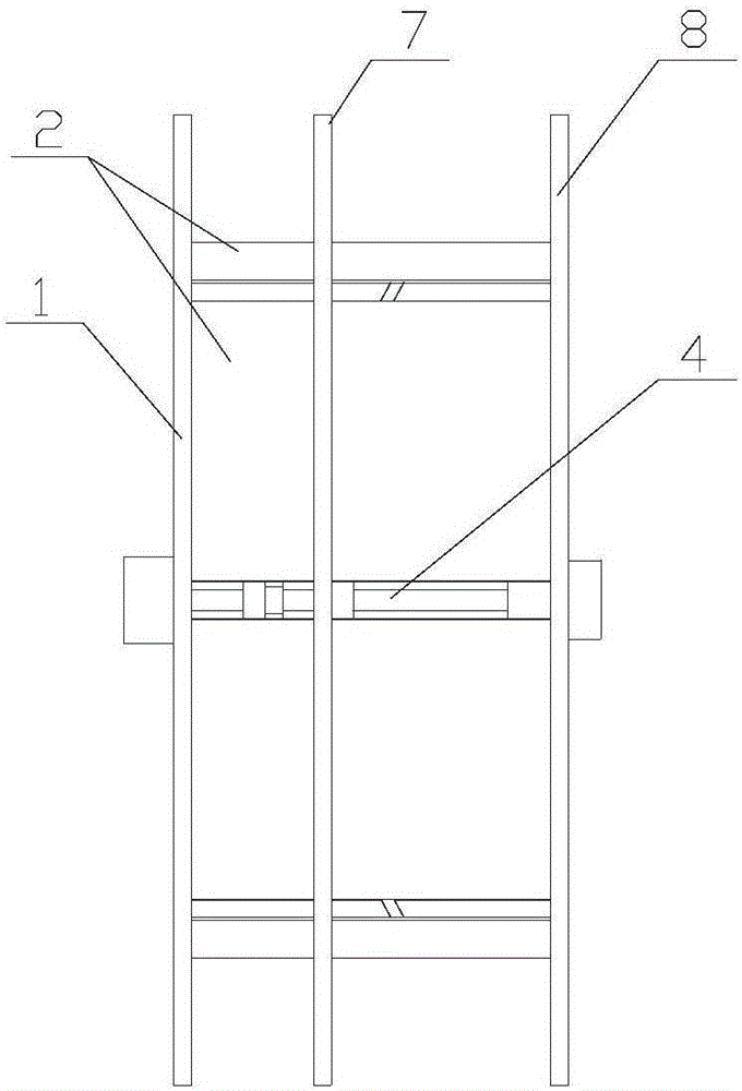
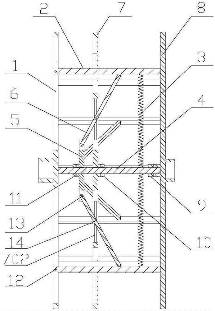
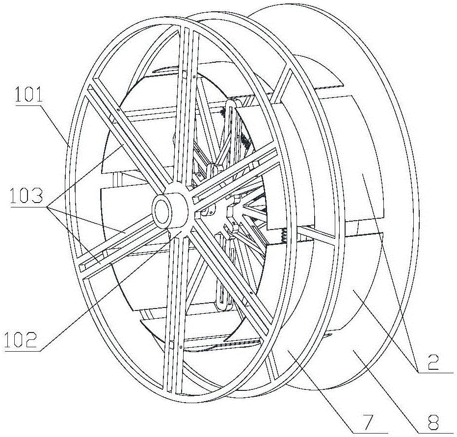
[0037] figure 1 , figure 2 , image 3 It shows a shrinkable loose winding reel for optical cable testing, including a first fixed side plate 1, a second fixed side plate 8 and a central cylinder, the central cylinder is composed of six central cylinder plates 2 with the same circumferential width composition (such as Figure 8 shown), one end of the central tube plate 2 is pivotally connected to the first fixed side plate 1 through the tube plate positioning shaft 12, and the other end of the central tube plate 2 is matched with the second fixed side plate 8 Bonding; there is an effective distance between two adjacent central tube plates 2 so that the central tube plate 2 can be turned inward at an effective angle at the same time (in use, so that the optical cable on the reel can be in the loose winding required by the test. state), such as Figu...


PUM


Abstract

The invention discloses a retractable loose winding reel for optical cable testing, which comprises a fixed side plate and a central tube composed of several central tube plates, one end of the central tube plate is axially connected with the first fixed side plate, and the first and second fixed sides The plate is fixedly connected to the central shaft; the central shaft is provided with a positioning plate and a support plate, the central tube plate passes through the positioning plate, and the support plate is fixedly sleeved on the central shaft to adjust the axial position; the support plate and the central tube plate A number of support rods are arranged for matching between the support rods, and the inner ends of the support rods are matched with the shaft joints of the support plate and the outer ends are matched with the center tube plate; the smooth limit pins of the support rods are limited smoothly in the limit guide grooves of the positioning plate, and the inside of the center tube plate is set An extension spring is arranged, and the other end of the extension spring is hinged with the central shaft. The structure of the reel of the present invention is ingenious and reasonable, without going through the traditional complicated disassembly and assembly process, it only needs to be assembled, and after adjusting the width of the take-up reel, adjust the position of the support plate to realize the contraction of the reel and make the optical cable into a loose winding state, which is very time-saving save effort.

Description

technical field [0001] The invention relates to a testing device, in particular to a reel for optical cable testing. The optical cable can be loosely wound on the reel to perform corresponding performance tests. Background technique [0002] With the development of modern science and technology, people's life and work are increasingly inseparable from network and communication, which promotes the rapid development of optical communication technology. With the continuous requirements for the scale and speed of communication by the development of technology, people's requirements for the stability and reliability of optical communication are also constantly increasing. This requires us to put forward high requirements for the performance test of optical cables in the production of optical cable equipment. Among them In the temperature cycle test link, it is required that the optical cable is subjected to a temperature cycle test under the condition of a loose winding reel. At...

Claims


Application Information

Patent Timeline
Patent Type & Authority Applications(China)
IPC IPC(8): B65H75/22B65H75/14G01M11/00
CPCB65H75/22B65H75/14G01M11/00
Inventor 周彩玲符剑松谢华杨向荣
Owner YANGTZE OPTICAL FIBRE & CABLE (SHANGHAI) CO LTD
Learn More