Bidirectional limiting device swinging based on tension of steel wire rope

A two-way limit and wire rope technology, which is applied in the field of limit devices and wire rope guides, can solve the problems of inability to achieve accurate limit and accurate monitoring of wire rope tasks, and achieve the effects of convenient operation, increased life, and reduced wear

Inactive Publication Date: 2017-06-13
中国人民解放军63729部队 +1
View PDF8 Cites 3 Cited by
  • Summary
  • Abstract
  • Description
  • Claims
  • Application Information

AI Technical Summary

Problems solved by technology

Most of the existing technologies simply use the steel wire rope to wrap it tightly around the drum in an orderly manner. The actual limit position is determined by the length of the steel wire rope. The corresponding position, so it is often impossible to achieve a convenient and reliable accurate limit, and it is also impossible to accurately monitor whether the wire rope has completed the task

Method used


Image

  • Bidirectional limiting device swinging based on tension of steel wire rope
  • Bidirectional limiting device swinging based on tension of steel wire rope
  • Bidirectional limiting device swinging based on tension of steel wire rope

Examples


Embodiment Construction

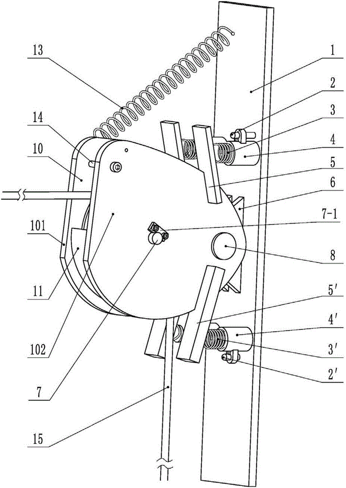
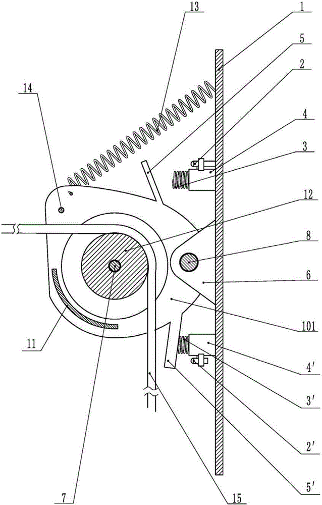
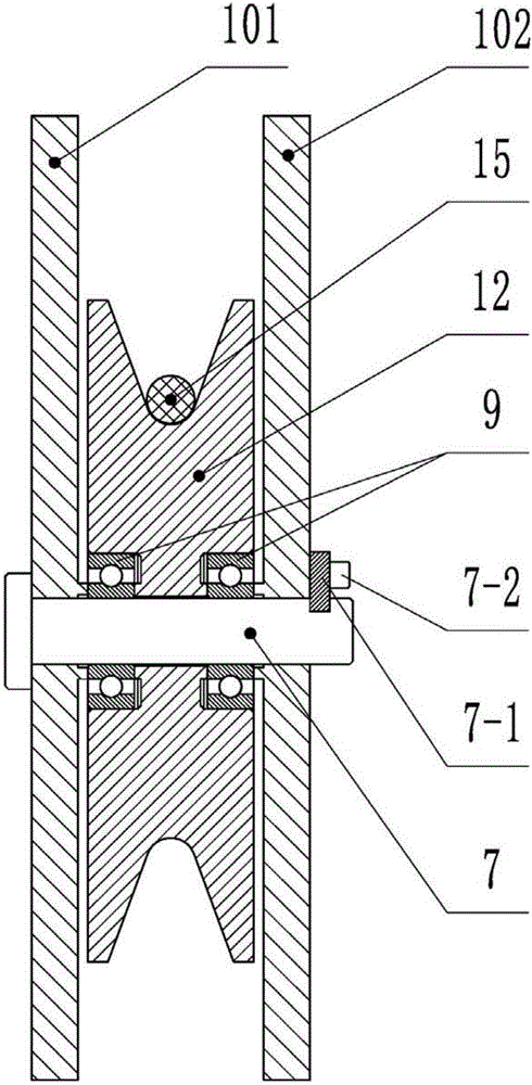
[0012] Such as Figure 4 As shown, the steel wire rope 15 set in the "V" groove of the guide wheel 12 is in a loose state. At this time, the guide wheel frame 10 will rotate upward around the support pin shaft 8 under the action of the tension spring 13, but it is limited by the limit bolt 14. The blocking of the groove will not occur, and at the same time, the upper limit pressure plate 5 is in conflict with the buffer spring 3, which plays a buffer role; Figure 5 It is shown that the steel wire rope 15 is in a tensioned state. At this time, the guide wheel frame 10 will rotate downward around the support pin shaft 8, and the tension will be slowed down by the action of the tension spring 13, so as to overcome the excessive friction loss. At the same time, The lower limit pressure plate 5' is in conflict with the lower buffer spring 3' to play a buffering role.


PUM


Abstract

The invention relates to a bidirectional limiting device swinging based on tension of a steel wire rope. The device comprises a base, a guide wheel rack, a guide wheel and a steel wire rope. The device is characterized in that the guide wheel rack is fixed on the base through a bearing pin roll; the guide wheel is mounted on a central shaft of the guide wheel rack through a bearing, the central shaft is fixedly connected to the guide wheel rack through a shaft lock and a screw, upper and lower sleeves are separately mounted on the upper and lower portions of the bearing pin roll on a panel of the base, the upper and lower sleeves sleeve outside buffer springs, distance sensors are separately mounted on the outer surfaces of the upper and lower sleeves, upper and lower limiting plates are separately located in positions corresponding to the upper and lower buffer springs, and the bottom ends of the upper and lower limiting plates are fixedly connected to the guide wheel rack; a tension spring is mounted on the upper portion of the guide wheel rack, and the upper end of the tension spring is connected to the base while the lower end of the tension spring is connected to the guide wheel rack; and the limiting bolt is mounted on the left upper portion of the guide wheel rack. The device provided by the invention has the advantage of preventing the steel wire rope from jumping from a slot due to an over-large rope angle or excessive wear caused by an over-small rope angle and reducing an impact vibration phenomenon.

Description

technical field [0001] The invention belongs to the field of wire rope guiding and limiting devices, in particular to a two-way motor limiting device based on the tension swing of the steel wire rope. Background technique [0002] At present, in the device for adjusting the position of the working platform by using the motor to pull the steel wire rope, the main problems faced are firstly to prevent the steel wire rope from falling out of the groove due to excessive rope angle, and secondly to ensure the precise positioning of the working platform. Most of the existing technologies simply use the steel wire rope to wrap it tightly around the drum in an orderly manner. The actual limit position is determined by the length of the steel wire rope. Corresponding position, often can not reach convenient and reliable accurate limit like this, also can't accurately monitor whether the wire rope completes the operation task simultaneously. Contents of the invention [0003] The o...

Claims


Application Information

Patent Timeline
Patent Type & Authority Applications(China)
IPC IPC(8): B66D1/36B66D1/56
CPCB66D1/36B66D1/56
Inventor 张平齐向东刘汉滨董富治苏佳易思
Owner 中国人民解放军63729部队
Why Eureka
Try Eureka