Fully automatic heat treatment industrial furnace

An industrial furnace, fully automatic technology, used in heat treatment furnaces, heat treatment equipment, heat treatment process control and other directions, can solve the problems that cannot be installed in the furnace body, the heating workpiece is difficult to achieve the same temperature, the operation is laborious and laborious, and the surface of the shell can be guaranteed. The temperature and graphic operation interface is convenient, and the effect of preventing uneven force

Active Publication Date: 2018-06-29
SHANGHAI JVJING PRECISION INSTR MFG
View PDF5 Cites 0 Cited by
  • Summary
  • Abstract
  • Description
  • Claims
  • Application Information

AI Technical Summary

Problems solved by technology

[0005] 1. The heat treatment workpiece is manually pushed into the heating furnace body, and the workpiece heated to high temperature needs to be taken out. The whole process will expose the operator to the heat of high temperature radiation, which will affect the health of the operator;
[0006] 2. The heating furnace body is made of refractory bricks, which has poor thermal insulation effect and no energy saving. The surface temperature of the furnace body is high. The bottom push-pull chassis and the heating furnace body are not tightly sealed, and a lot of heat will escape. The temperature field in the furnace body is uniform Not good, it is difficult to heat the workpiece to achieve consistent temperature;
[0007] 3. The bottom push-pull chassis has no lifting function. When the height of the heat treatment workpiece is large, the existing structure cannot be installed inside the furnace body;
[0008] 4. The structure and function are single, and it can only be adapted to simple heat treatment procedures. The operation is laborious and laborious, and the system cannot be applied to automatic assembly lines.

Method used


Image

  • Fully automatic heat treatment industrial furnace
  • Fully automatic heat treatment industrial furnace
  • Fully automatic heat treatment industrial furnace

Examples


Embodiment Construction

[0070] In order to describe the technical content of the present invention more clearly, further description will be given below in conjunction with specific embodiments.

[0071] In order to solve the above technical problems, the fully automatic heat treatment industrial furnace of the present invention adopts the following technical solutions:

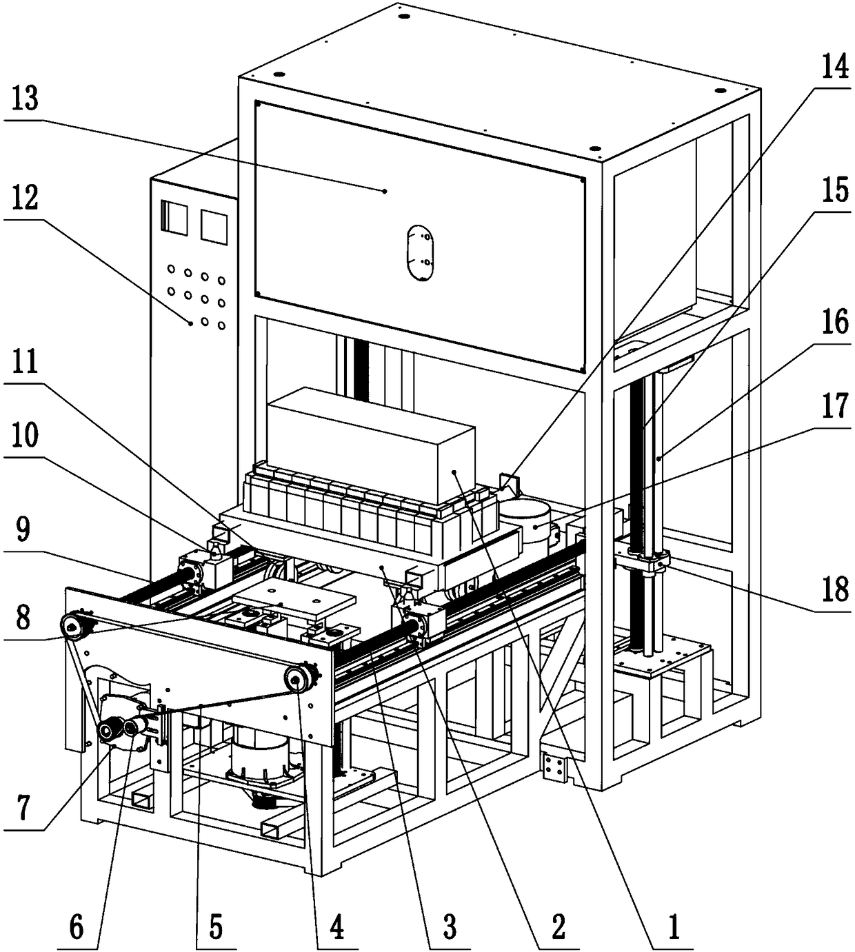
[0072] like figure 1 As shown, it consists of workpiece, mobile trolley, translation drive mechanism, lifting drive mechanism, heating furnace, automatic weighing mechanism and automatic control system. The workpiece 1 is placed on the mobile trolley 2, and the mobile trolley 2 is equipped with a multi-layer refractory brick building insulation plate that can carry the workpiece 1, and can perform translation and lifting movements under the control of the automatic control system. There are 4 rollers 11 at the bottom of the mobile trolley 2. Preferably, V-shaped rollers can be used. Driven by the translation drive motor 7, the sync...


PUM


Abstract

The invention relates to a full-automatic heat treatment industrial furnace. The full-automatic heat treatment industrial furnace comprises a heating furnace, a movable bearing device, a translation mechanism, a lifting mechanism, an automatic weighing mechanism and an automatic control system, the automatic control system controls the movable bearing device to achieve horizontal movement through the translation mechanism, and makes a workpiece to be subjected to heat treatment enter the inside of the heating furnace from the bottom of the heating furnace through the lifting mechanism, the end of the translation mechanism is provided with a weighing mechanism for automatically weighing the workpiece to be subjected to the heat treatment, the weighing mechanism comprises a weighing driving motor and a double screw rod synchronous lifting mechanism which is driven by a weighing synchronous belt, the upper end of the double screw rod synchronous lifting mechanism driven by the weighing synchronous belt is provided with a lifting plate, and the upper part of the weighing lifting plate is provided with a weighing table and a weighing sensor which is arranged between the lifting plate and the weighing table. By adopting the full-automatic heat treatment industrial furnace, operation and debugging are convenient, and the precision is high.

Description

technical field [0001] The invention relates to the field of machinery, in particular to material heat treatment equipment, in particular to a fully automatic heat treatment industrial furnace. Background technique [0002] In the field of workpiece processing technology, there are some hard or sticky workpieces that are not easy to cut and grind. Usually, these workpieces need to be heat treated to change the inherent characteristics of the material itself and improve the machinability of the workpiece. . The heat treatment industrial furnace currently used in the market is a kind of heat treatment industrial furnace with a push-pull device at the bottom. The workpieces that need to be heat-treated during the working process of the system are placed on the bottom plate with the push-pull device, and the workpieces are pushed into the heating furnace by manual operation. , the heating furnace is an electric heating furnace, the insulation layer is made of refractory bricks,...

Claims


Application Information

Patent Timeline
Patent Type & Authority Patents(China)
IPC IPC(8): C21D9/00C21D11/00
CPCC21D9/005C21D11/00
Inventor 李帅帅邹方张上荣
Owner SHANGHAI JVJING PRECISION INSTR MFG
Why Eureka
Try Eureka