Construction method of flow plastic-state sludge sand stratum diaphragm wall

A construction method and silt technology, applied in sheet pile wall, foundation structure engineering, earth mover/shovel, etc., can solve the problem that the ground connection wall occupies the used space, the reinforcement cage cannot be installed smoothly, and the land connection is occupied. Wall construction axis and other issues, to achieve the effect of improving the brushing effect, improving the construction progress of the trough, and ensuring the verticality of the trough

Pending Publication Date: 2017-06-13
SINOHYDRO FOUND ENG
View PDF5 Cites 0 Cited by
  • Summary
  • Abstract
  • Description
  • Claims
  • Application Information

AI Technical Summary

Problems solved by technology

[0003] However, due to the influence of various factors such as geological conditions, some of the groove wall retaining piles will be inclined, so the construction axis of the ground connection wall is seriously encroached, making the hydraulic groove forming machine very easy to deflect during the groove forming process
Since the reinforcement cage of the ground connection wall is installed under the groove at one time, a slight deviation of the slot hole will not only cause the reinforcement cage to not be installed smoothly, but also cause the ground connection wall to occupy other adjacent used spaces after excavation. Therefore, The verticality of the slot hole must be ensured during the slotting process, otherwise once the above situation occurs, the construction progress will be seriously affected

Method used


Image

  • Construction method of flow plastic-state sludge sand stratum diaphragm wall
  • Construction method of flow plastic-state sludge sand stratum diaphragm wall
  • Construction method of flow plastic-state sludge sand stratum diaphragm wall

Examples


Embodiment Construction

[0050] The invention provides a construction method for a ground connection wall in a flow-plastic silty sand-containing stratum, comprising:

[0051] Convective plastic muddy sandy stratum is used for trenching construction in order to form ground connection wall slots;

[0052] Carry out reinforcement cage lowering and concrete pouring construction in the slot hole to form the ground connecting wall;

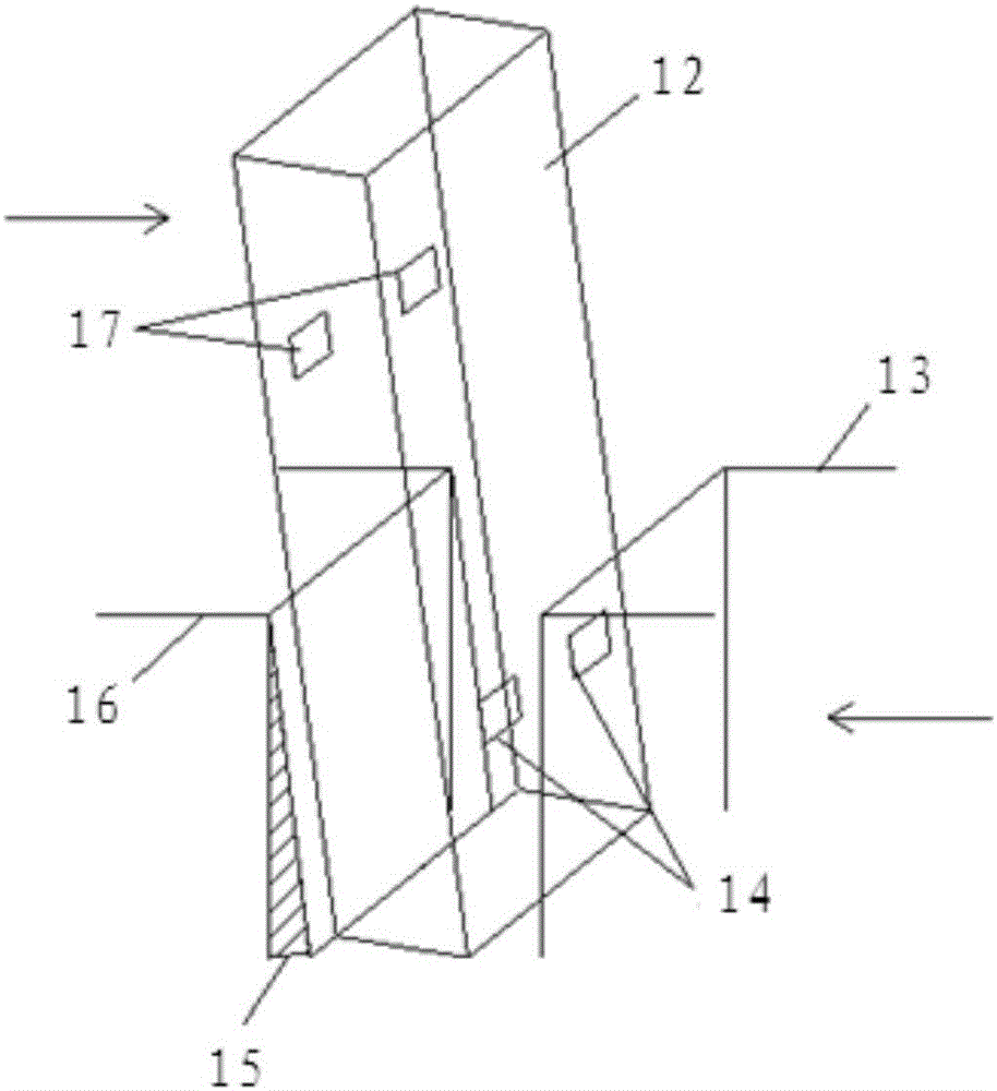
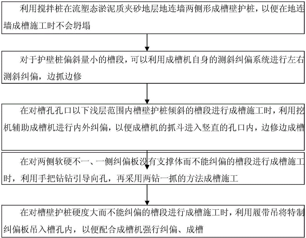
[0053] Among them, the trenching construction process in the convective plastic silty sandy stratum includes the step of trenching and rectifying deviation, and the steps include:

[0054] Use stirring piles to form groove wall protection piles on both sides of the ground connection wall in the flow-plastic silt sandy stratum, so that the ground connection wall will not collapse during the construction of the groove;

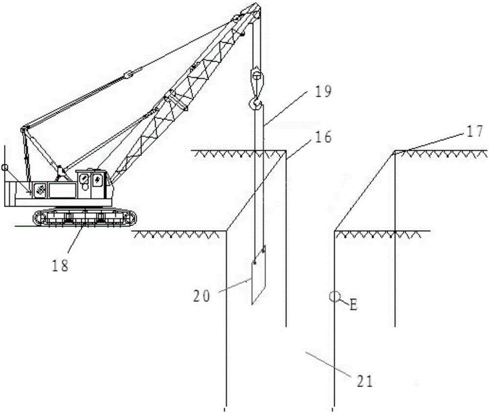
[0055]When performing groove construction on the inclined groove section of the groove wall protection pile in the shallow range below the hole opening, the ex...


PUM


Abstract

The invention discloses a construction method of a flow plastic-state sludge sand stratum diaphragm wall. The method comprises the steps of forming a diaphragm wall through diaphragm wall slot and concrete pouring, wherein slot construction comprises grooving and rectifying steps; forming slotted wall guard piles at two sides of a flow plastic-state sludge sand stratum diaphragm wall by adopting a stirring pile; and assisting a grooving machine in inner and outer rectification by using an excavator during grooving construction on inclined groove segments of the slotted wall guard piles with a shallow range below a slot opening, entering a grab bucket of the grooving machine into a vertical opening and grooving while trimming, wherein the step of assisting a grooving machine in inner and outer rectification by using the excavator is that the excavator pushes the upper part of the grab bucket body, so that the lower part of the grab bucket body reversely moves relative to the upper part of the grab bucket body to push the inclined slotted wall guard piles through the grab bucket and to strengthen the inclined slotted wall guard piles. According to the method, the perpendicularity of the slot is ensured through fast and effective correction in the diaphragm wall grooving process, the leakage condition of the diaphragm wall is effectively prevented and the construction period is shortened.

Description

technical field [0001] The invention relates to the field of water conservancy and hydropower engineering, in particular to a construction method for a connecting wall of a flow-plastic silty sand-containing stratum. Background technique [0002] With the rapid development of domestic water conservancy and hydropower engineering construction, the treatment scope, depth, and stratum structure are becoming more complicated and diversified. In the prior art, when the ground connection wall construction is carried out for the project engineering with flow-plastic silty sandy strata, in order to ensure the stability of the groove wall and prevent the ground connection wall from collapsing during the formation of the groove, it is often used On both sides of the ground connection wall, three-axis mixing piles are used as the groove wall protection piles. [0003] However, due to the influence of various factors such as geological conditions, part of the groove wall retaining pile...

Claims


Application Information

Patent Timeline
IPC IPC(8): E02D5/18E02F5/02
CPCE02D5/187E02F5/025
Inventor 赵瑞峰李伟崔文光刘勇惠高飞郑伟朱永建高大起柴永辉孙亮
Owner SINOHYDRO FOUND ENG
Why Eureka
Try Eureka