Heavy-duty demolition apparatus with replaceable tip and rotatable cross blade

Inactive Publication Date: 2005-08-09
GENESIS ATTACHMENTS
View PDF52 Cites 55 Cited by
  • Summary
  • Abstract
  • Description
  • Claims
  • Application Information

AI Technical Summary

Benefits of technology

[0009]A principal object and advantage of the present invention is that the cross blade, mounted at an angle to the tie plate, assists in producing flat scrap producing maximum storage and transport by allowing the upper shear blade to clear the cross blade more easily after initial scrap piercing and shearing.
[0010]Another principal object and advantage of the present invention is that the cross blade is rotatably mounted with four cutting surfaces that may be brought into position for shearing.
[0011]Another principal object and advantage of the present invention is that a rep

Problems solved by technology

Prior art shears have several problems.
During the shearing process, metal scrap may become twisted and/or bent.
Thus, sometimes the scrap or work piece gets jammed or wedged in the shear, requiring down time to cut the scrap out of the

Method used


Image

  • Heavy-duty demolition apparatus with replaceable tip and rotatable cross blade
  • Heavy-duty demolition apparatus with replaceable tip and rotatable cross blade
  • Heavy-duty demolition apparatus with replaceable tip and rotatable cross blade

Examples


Embodiment Construction

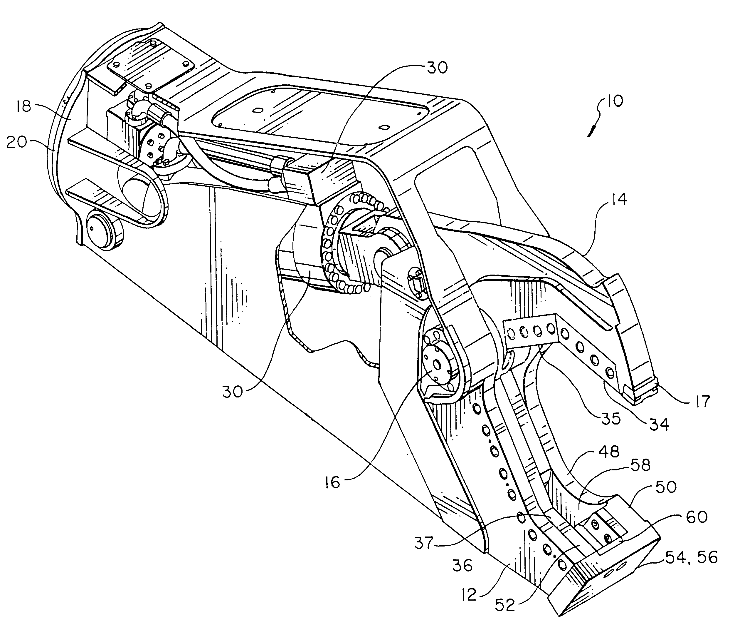
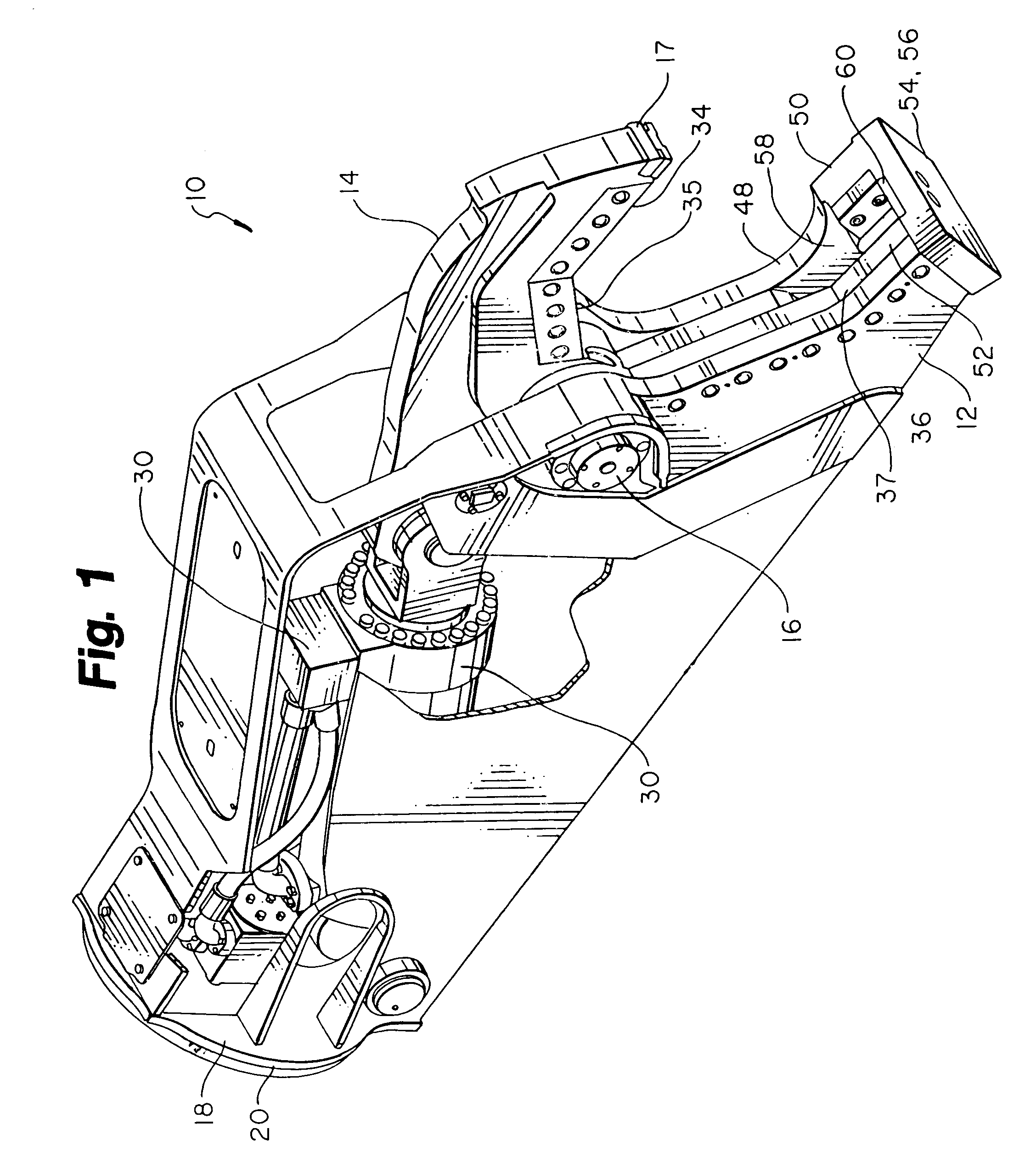
[0024]The heavy-duty demolition apparatus of the present invention is generally referred to in the Figures as reference numeral 10.

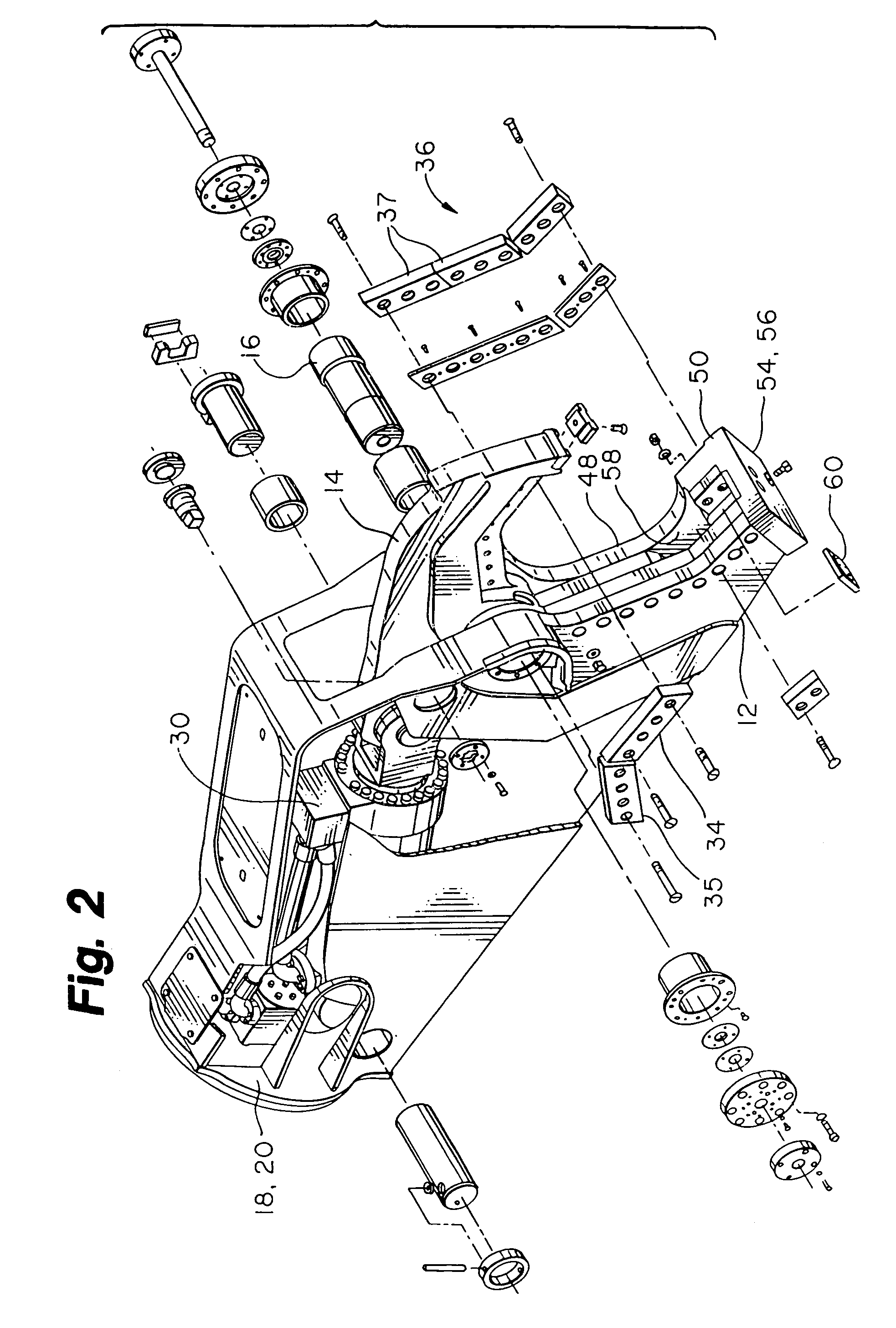
[0025]Referring to FIGS. 1 through 6, the heavy-duty demolition apparatus or shear 10 comprises a lower jaw 12, an upper jaw 14, pivot means 16 interconnecting the lower jaw 12 and upper jaw 14, and means 18 for attachment to the excavator. The means 18 may further include a rotator unit 20 allowing rotation of the demolition unit 10 about a longitudinal axis. The apparatus 10 also includes means 30 for attachment to the hydraulic system of an excavator (not shown) for closing and opening the upper jaw relative to the lower jaw.

[0026]The upper jaw 14 has an upper shear secondary blade 34 and primary blade 35. The lower jaw 12 has a lower secondary shear blade 36 and primary blade 37 extending along each other for shearing a workpiece when the upper shear blades 34 and 35 are closed upon the lower shear blades 36 and 37. Preferably, the shear blades 34, 3...


PUM

PropertyMeasurementUnit
Angleaaaaaaaaaa
Angleaaaaaaaaaa
Angleaaaaaaaaaa

Abstract

A heavy-duty demolition shear for attachment to the boom structure and hydraulic system of an excavator, has a rigid lower jaw and an upper jaw and pivot interconnecting the jaws together. The shear is attachable to the boom structure of the excavator. The upper jaw has upper shear blades, while the lower jaw has at least one lower shear blade. The lower jaw also has a rigid guide blade lying along the lower shear blade and in spaced relation therewith. The outer ends of the shear blade and guide blade are co-extensively opposed to each other so that a tie plate secures the outer ends of the lower shear blade and the guide blade together. There is an open slot between the lower shear blade and the adjacent guide blade to receive the upper shear blade and upper jaw therein. The upper jaw has a cylinder attached to the hydraulic system of the excavator for closing and opening the upper jaw relative to the lower jaw. The lower jaw and the upper jaw shear a workpiece when the upper jaw is closed upon the lower jaw. A rotatable, indexable cross blade is mounted to the tie plate substantially transverse to the lower shear blade and to the guide blade. The cross blade is seated and mounted inside the tie plate at an angle between one degree and thirty degrees, preferably about ten degrees. Thus, the cutting edge leans inwardly toward the throat of the shear, while the lower portion extends outwardly to provide upper jaw clearance within the open slot. The upper jaw includes a replaceable tip.

Description

[0001]This is a continuation-in-part of U.S. patent application Ser. No. 09 / 267,569, now U.S. Pat. No. 6,119,970 filed Mar. 12, 1999, which is a continuation-in-part of U.S. patent application Ser. No. 09 / 200,688, filed Nov. 25, 1998, now U.S. Pat. No. 6,061,911.BACKGROUND OF THE INVENTION[0002]An understanding of the operation of the demolition shears or apparati like the present invention may be learned by studying U.S. Pat. No. 4,519,135, hereby incorporated by reference. This invention relates to a heavy duty demolition apparatus, especially adapted to be mounted on a rigid boom of a mobile vehicle and particularly adapted to be mounted on the dipper stick of an excavator, with a blade stabilizing device to keep the upper jaw of the apparatus from moving laterally relative to the lower jaw and breaking during the shearing operation on a workpiece.[0003]Heavy duty shears of the type that are powered by hydraulic cylinders are proving more and more useful in handling scrap and esp...

Claims


Application Information

Patent Timeline
IPC IPC(8): B23D17/00E02F3/04E02F3/96E04G23/08
CPCB23D17/00E02F3/965E04G23/08E04G23/082
Inventor LABOUNTY, KENNETH R.CHRISTENSON, ROSS D.JACOBSON, DANIEL P.
Owner GENESIS ATTACHMENTS
Why Eureka
Try Eureka