Electromagnetic brake control circuit and electromagnetic brake controller

A control circuit, electromagnetic brake technology, applied in the direction of brake actuators, gear shifting mechanisms, mechanical equipment, etc., can solve the problems of shortening the life of the brake, reducing the winding current, waste of electric energy, etc., and reducing the brake control. , the effect of prolonging the service life

Inactive Publication Date: 2017-06-13
深圳锐特机电技术有限公司
View PDF6 Cites 3 Cited by
  • Summary
  • Abstract
  • Description
  • Claims
  • Application Information

AI Technical Summary

Problems solved by technology

In the normal temperature state, excess voltage is applied to the winding, and the excess energy will cause the temperature of the winding to rise rapidly, which in turn will lead to an increase

Method used


Image

  • Electromagnetic brake control circuit and electromagnetic brake controller
  • Electromagnetic brake control circuit and electromagnetic brake controller
  • Electromagnetic brake control circuit and electromagnetic brake controller

Examples


Embodiment Construction

[0025] The following will clearly and completely describe the technical solutions in the embodiments of the present invention with reference to the accompanying drawings in the embodiments of the present invention. Obviously, the described embodiments are only part of the embodiments of the present invention, not all of them. Based on the embodiments of the present invention, all other embodiments obtained by persons of ordinary skill in the art without creative efforts fall within the protection scope of the present invention.

[0026] It should be noted that all directional indications (such as up, down, left, right, front, back...) in the embodiments of the present invention are only used to explain the relationship between the components in a certain posture (as shown in the accompanying drawings). Relative positional relationship, movement conditions, etc., if the specific posture changes, the directional indication will also change accordingly.

[0027] In addition, the ...


PUM


Abstract

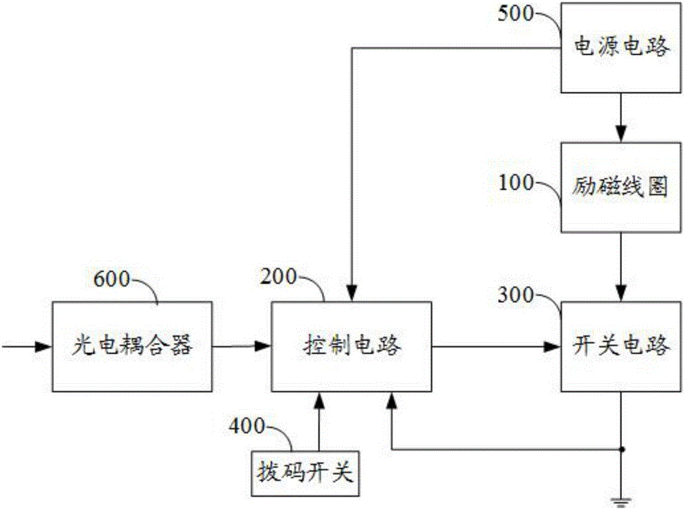
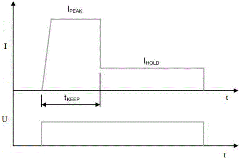
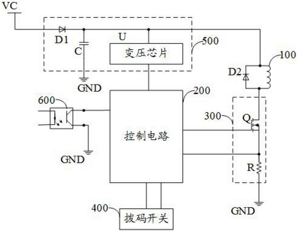
The invention discloses an electromagnetic brake control circuit and an electromagnetic brake controller. The electromagnetic brake control circuit comprises an excitation coil, a control circuit and a switch circuit, wherein the control circuit outputs a brake turning-on signal or a brake keeping signal; the switch circuit receives the brake turning-on signal or the brake keeping signal, performs turning on or turning off, and controls the magnitude of currents passing the excitation coil; the excitation coil controls the armature of a brake to loosen a brake disc when the control circuit outputs the brake turning-on signal; the excitation coil controls the armature of the brake to be separated from the brake disc when the control circuit outputs the brake keeping signal. The electromagnetic brake control circuit has the advantages that the heat generation quantity of the electromagnetic brake is reduced by using the current control manner, and the service life of the brake is prolonged.

Description

technical field [0001] The invention relates to the technical field of electromechanical control, in particular to an electromagnetic brake control circuit and an electromagnetic brake controller. Background technique [0002] The electromagnetic brake device is widely used in various transmission devices that need to maintain the position after power failure. The electromagnetic brake is mainly composed of an excitation coil, a spring, and an armature. When the excitation coil is energized, a magnetic field is generated, and the armature is attracted to loosen the armature and the brake disc. Open; when the excitation coil is powered off, the magnetic field disappears, and the armature is pushed to the brake disc by the action of the spring, generating friction torque and braking. At present, the control method of the electromagnetic brake adopts the voltage control mode. The winding of the electromagnetic brake is usually made of copper. As the temperature rises, the resis...

Claims


Application Information

Patent Timeline
IPC IPC(8): F16D65/22F16D121/22
CPCF16D65/22F16D2121/22
Inventor 赖九才
Owner 深圳锐特机电技术有限公司
Why Eureka
Try Eureka