Vibration proof device with bracket

A technology of anti-vibration device and bracket, which is applied in the direction of power plant, jet propulsion device, internal combustion propulsion device, etc. It can solve the problems of rubber layer damage, increase of elastic coefficient, and difficulty in realizing anti-vibration performance, so as to reduce impact, Excellent and durable effect

Active Publication Date: 2017-06-13
SUMITOMO RIKO CO LTD
View PDF8 Cites 7 Cited by
  • Summary
  • Abstract
  • Description
  • Claims
  • Application Information

AI Technical Summary

Problems solved by technology

[0007] However, in the structure of Patent Document 1 in which the rubber layer is integrally formed with the rubber elastic body, there is a problem that it is difficult to achieve both the properties required for the rubber elastic body and the properties required for the rubber layer.
That is, the rubber elastic body needs a relatively soft elastic coefficient in order to facilitate the vibration-proof performance caused by elastic deformation. The load capacity becomes insufficient, and the rubber layer may be damaged when the stopper contacts.
On the other hand, when trying to set a large elastic coefficient that can sufficiently satisfy the load resistance in the rubber layer, the elastic coefficient of the rubber elastic body also increases, and it is difficult to achieve the intended anti-vibration performance.

Method used


Image

  • Vibration proof device with bracket
  • Vibration proof device with bracket
  • Vibration proof device with bracket

Examples


Embodiment Construction

[0043] Embodiments of the present invention will be described below with reference to the drawings.

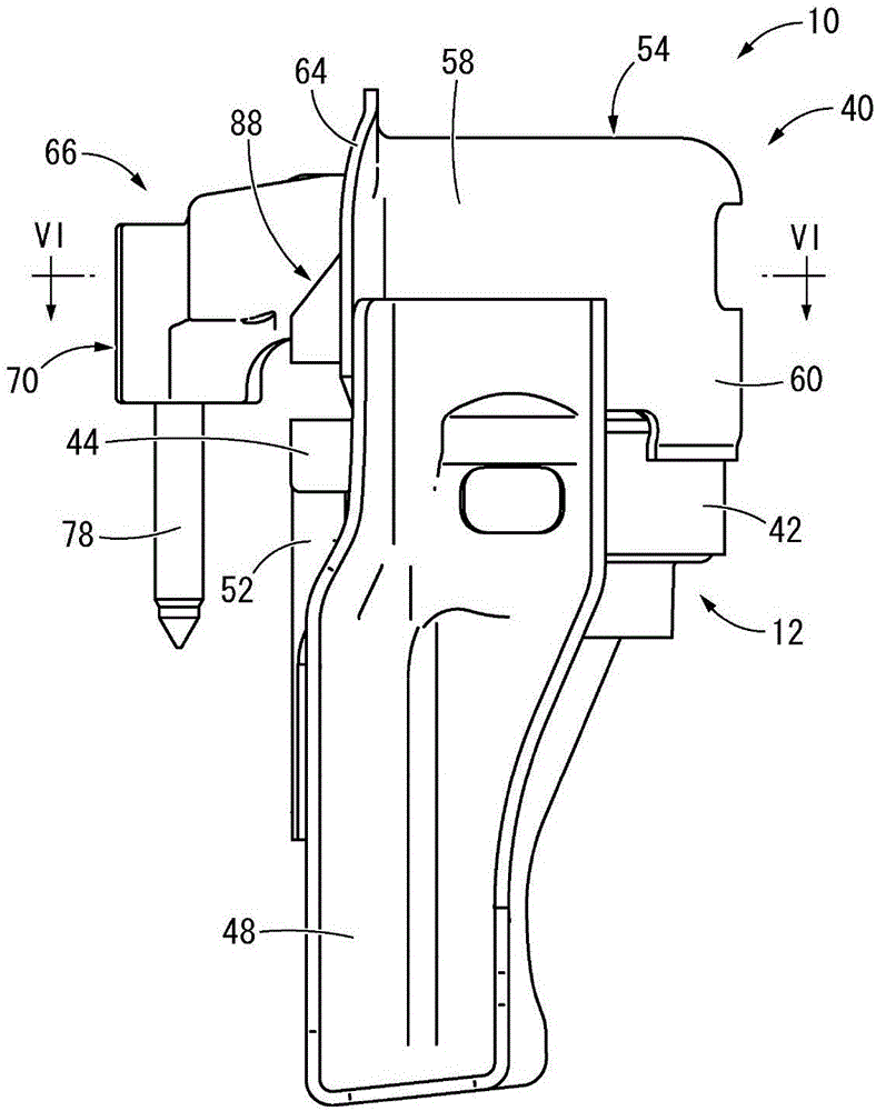
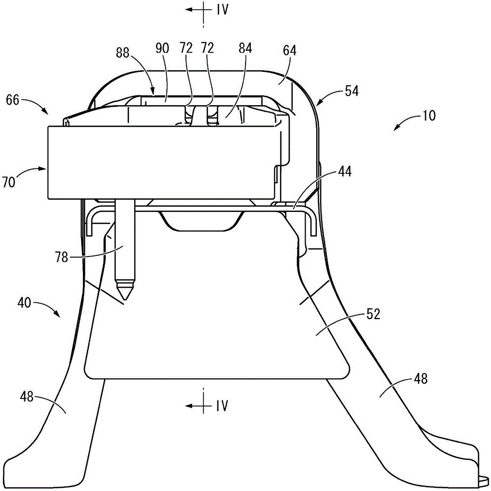
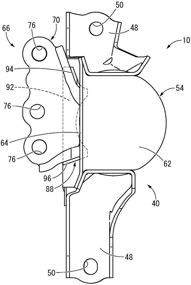
[0044] exist Figure 1 ~ Figure 3 In , an engine mount 10 for an automobile is shown as a first embodiment of a vibration isolator employing the structure according to the present invention. The engine bracket 10 has a bracket main body 12, such as Figure 4 , 5 As shown, the bracket main body 12 has a structure in which the first mounting member 14 and the second mounting member 16 are elastically connected to each other by a main body rubber elastic body 18 . In the following description, in principle, the vertical direction refers to the central axis direction of the support and the main vibration input direction is figure 1 in the up and down direction. In addition, the left-right direction refers to the left-right direction of the vehicle in the vehicle-mounted state, respectively. image 3 The left and right directions, the front and rear directions refer to the fr...


PUM


Abstract

Provide is a vibration proof device with a bracket of a new structure which can make compatible the demand characteristic of a main part rubber elasticity object, and the demand characteristic of stopper rubber, and can obtain the vibration-proof performance made into the object, and a buffer stopper operation. In a vibration proof device with a bracket, a main part rubber elasticity object (18) and a first stopper rubber (32) integrally formed are provided by a first mounting member 1(4,); a second stopper rubber (88) which was formed by the main part rubber elasticity object (18) and a separate body, and was enlarged in a spring constant rather than the first stopper rubber (32) is provided by a bracket (66), a stopper has a stopper rubber abutment surface which abuts with the first stopper rubber (32) and the second stopper rubber (88), and restricts the amount of elastic deformation of the main part rubber elasticity object (18) by relative displacement of the first mounting member (14) and the second mounting member (16), and there is. In a stopper, the first stopper rubber (32) is close to a stopper rubber abutment surface rather than the second stopper rubber (88).

Description

[0001] Cross References to Related Applications [0002] This application claims priority to Japanese Patent Application JP2015-226333 entitled "ブラケット付き Anti-vibration Device (Anti-vibration Device with Bracket)" filed on November 19, 2015, the entire content of which application is incorporated by reference In this article. technical field [0003] The present invention relates to an anti-vibration device with a bracket used for engine mounts and the like of automobiles. Background technique [0004] Conventionally, as a kind of anti-vibration supporting body or anti-vibration connecting body arranged between the components constituting the vibration transmission system and connecting the components of these vibration transmission systems to each other in vibration isolation, a vibration isolation device is known. The device is applied to, for example, an engine mount of an automobile or the like. As disclosed in, for example, Japanese Patent Application Laid-Open No. 20...

Claims


Application Information

Patent Timeline
Patent Type & Authority Applications(China)
IPC IPC(8): F16F15/08B60K5/12
CPCB60K5/1225B60K5/1266F16F15/08B60K5/12B60K5/1208B60K5/1291F16F13/085F16F3/093F16F2230/007F16F2230/02F16F1/3849F16F2226/045
Inventor 清水赖重日比悟园部修也
Owner SUMITOMO RIKO CO LTD
Why Eureka
Try Eureka