Fillet weld leg dimension and internal defect ultrasonic nondestructive measurement method

A technology for welding leg size and internal defects, applied in measuring devices, using ultrasonic/sonic/infrasonic waves, using sound waves/ultrasonic/infrasonic waves to analyze solids, etc., can solve the problem that it is difficult to obtain the welding leg size and the waveform read by the data gate is not accurate enough , the difficulty of accurate evaluation of the actual component strength and other issues, to achieve the effect of fast ultrasonic scanning speed and high detection accuracy

Active Publication Date: 2017-06-13
CRRC QINGDAO SIFANG CO LTD
View PDF18 Cites 9 Cited by
  • Summary
  • Abstract
  • Description
  • Claims
  • Application Information

AI Technical Summary

Problems solved by technology

Since it is impossible to measure the damage of the actual welded components, it is difficult to obtain accurate weld leg size, which brings difficulties to the a

Method used


Image

  • Fillet weld leg dimension and internal defect ultrasonic nondestructive measurement method
  • Fillet weld leg dimension and internal defect ultrasonic nondestructive measurement method
  • Fillet weld leg dimension and internal defect ultrasonic nondestructive measurement method

Examples


Embodiment 1

[0043] This embodiment provides an ultrasonic non-destructive measurement method for the size of the weld leg of an aluminum alloy fillet weld:

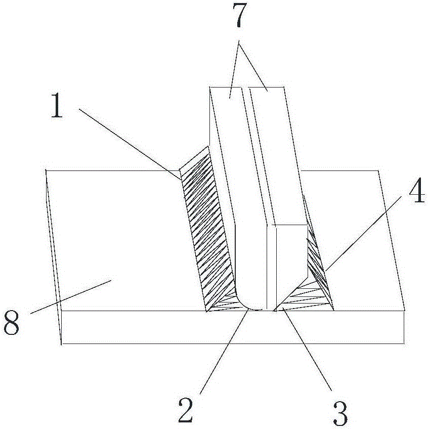
[0044] It includes a first welded plate, and welds a second welded plate with a welded area at a certain angle with the first welded plate. The welded area includes a fillet weld or an unfused hole. The weld term of the fillet weld structure is based on GB / T3375-94 Definitions of Welding Terms.

[0045]Preferably, the first welding plate is vertically welded on the second welding plate, and the first welding plate and the second welding plate form a T shape after welding.

[0046] The first welding plate includes grooves for welding, or no grooves for welding;

[0047] Specific measurements include:

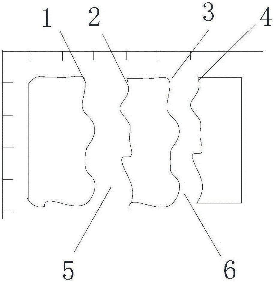
[0048] S1. Scanning the second welding plate to obtain the reflected echo of the target section;

[0049] S2. Perform visual scanning according to the reflected echo, and obtain a plan view of the target section represented by the e...

Embodiment 2

[0086] This embodiment provides an imaging method, including a phase imaging method. Ultrasonic reflected echoes contain amplitude and phase information, but commonly used ultrasonic equipment only uses echo amplitude information, and the actual echo signal phase also reflects the medium condition inside the object, even more sensitive. In this system, the phase difference is converted into gray value or color value for imaging.

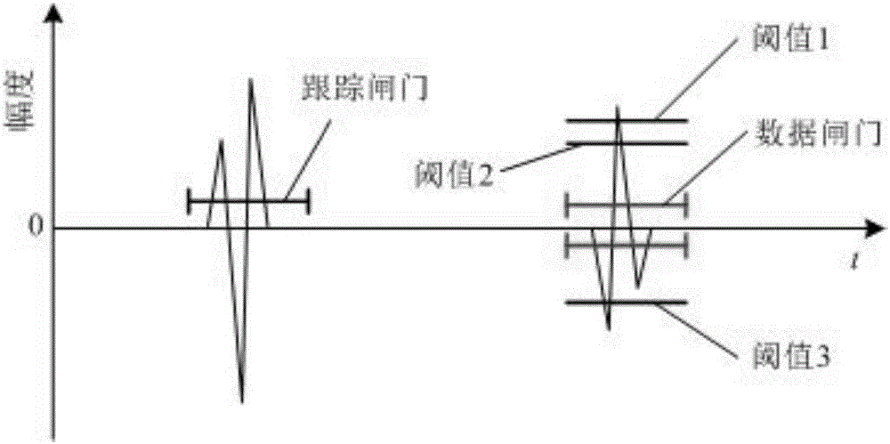
[0087] Further, the gray-scale plan includes obtaining the gray-scale plan by using phase imaging, and the phase imaging determines whether the phase of the waveform read by the second gate is reversed by setting the threshold value when the waveform data is read by the second gate .

[0088] The threshold is set to 2-4;

[0089] Preferably, the threshold includes 3, threshold 1, threshold 2 and threshold 3, wherein threshold 1 and threshold 2 are positive values, and threshold 3 is negative;

[0090] Optionally, the system can also use frequency ...


PUM


Abstract

The invention discloses a fillet weld leg dimension and internal defect ultrasonic nondestructive measurement method, which comprises a first welding plate and a second welding plate, wherein the second welding plate is welded in a way of forming a certain included angle with the first welding plate and is provided with a welding region; the welding region comprises fillet weld or non-fusion holes. The method comprises the following steps of scanning and inspecting the second welding plate; obtaining reflection echo of a target cross section; performing visual scanning and inspection according to the reflection echo; obtaining the target cross section plane graph represented by the echo; calculating the fillet weld leg or the non-fusion hole dimension according to the plane graph. By using the measurement method, the measurement is performed under the condition of not damaging the welding structure; the detection cross section and the inside non-fusion defect dimension can be accurately positioned; the detection result accuracy is improved; a beneficial technical method is provided for fillet weld structure intensity improvement, service life calculation and evaluation.

Description

technical field [0001] The invention belongs to the field of non-destructive measurement of fillet weld leg, in particular relates to an ultrasonic non-destructive measurement method for fillet weld leg size and internal defects. Background technique [0002] The weld seam is the weakest part of the welded structure, and most of the failure accidents of the welded structure are caused by the failure of the weld seam. Therefore, in order to ensure the quality of the welded structure, it is necessary to accurately obtain the key parameters of the weld seam after welding, and then evaluate the welding strength to ensure its Can meet the design requirements. In the prior art, in the aluminum alloy fillet weld structure, the method of destroying the process test piece before welding is mainly used to measure the size of the weld leg, and then determine a reasonable welding process. Since it is impossible to measure the damage of the actual welded components, it is difficult to o...

Claims


Application Information

Patent Timeline
IPC IPC(8): G01B17/00G01N29/06
CPCG01B17/00G01N29/043G01N29/069G01N2291/023G01N2291/267
Inventor 路浩何建英徐会庆
Owner CRRC QINGDAO SIFANG CO LTD
Why Eureka
Try Eureka