

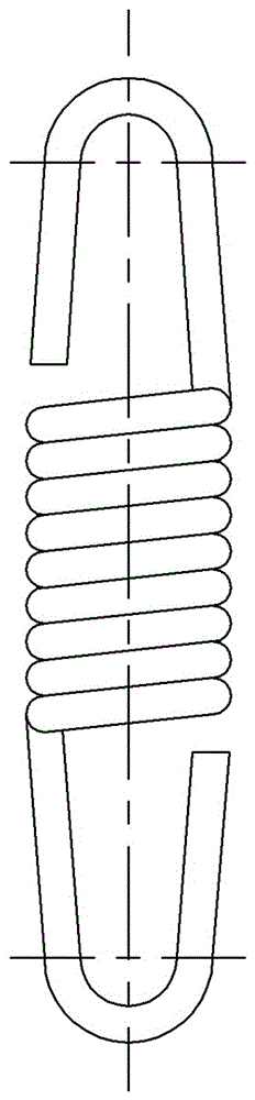
Crank-slider mechanism and spring life testing device with same
A technology of crank-slider mechanism and life test device, which is applied in the testing of machine/structural components, the testing of mechanical components, and the testing of material strength by applying repetitive force/pulsation force, etc. The effect of reducing crawling phenomenon, long service life and reducing wear and tear
- Summary
- Abstract
- Description
- Claims
- Application Information
AI Technical Summary
Problems solved by technology
Method used
Image

Examples
Embodiment Construction
[0039] Embodiments of the present invention will be further described below in conjunction with the accompanying drawings.
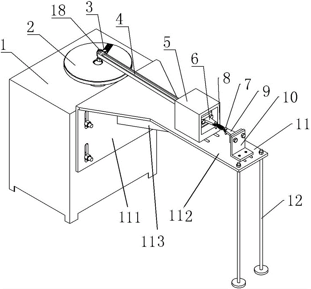
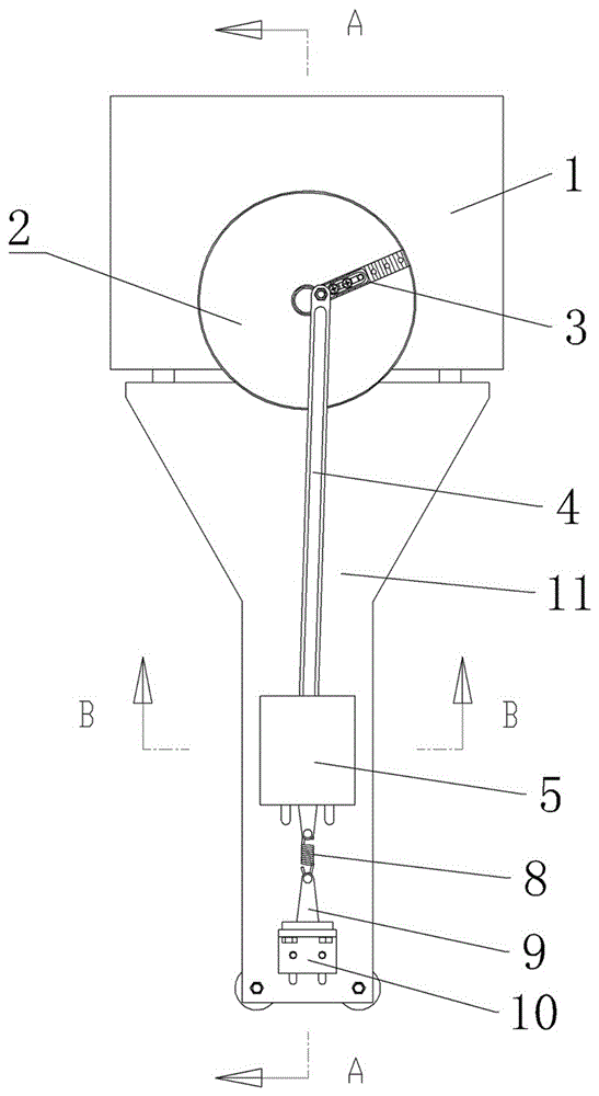
[0040] The specific embodiment 1 of a kind of spring life testing device of the present invention, as Figure 1 to Figure 19 As shown, the spring life test device includes a workbench, the workbench is mainly composed of a mechanism box 1 and a support frame 11, a reducer and a motor are arranged in the mechanism box 1, and the motor and the reducer together form the driving device of the spring life test device . The support frame 11 includes a vertical connecting plate 111 and a horizontal supporting plate 112, the vertical connecting plate 111 and the horizontal supporting plate 112 are integrally formed to form an L-shaped plate structure, the vertical connecting plate 111 is fixedly connected with the side wall of the mechanism box 1, and the mechanism The side wall of the box and the vertical connecting plate 111 are correspondingly provided with ...
PUM
 Abstract
Description
Claims
Application Information