A kind of vertical drilling coring machine and coring method with arbitrary positioning of specimen disk
A technology for drilling cores and specimens, applied in sampling devices and other directions, can solve the problems of inability to take cores multiple times, low efficiency of coring, time-consuming and laborious, etc., to improve the efficiency of coring, the structure is simple and reasonable, and the test environment is improved. Effect
- Summary
- Abstract
- Description
- Claims
- Application Information
AI Technical Summary
Problems solved by technology
Method used
Image
Examples
Embodiment 1
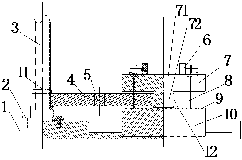
[0031] Such as figure 1 As shown, a vertical drilling and coring machine with arbitrarily positioned test piece trays includes a frame 3, a test piece tray 7, and a base 10. The frame 3 is fixed on the frame support 1 and the test piece tray 7 A clamp 6 is provided on it.
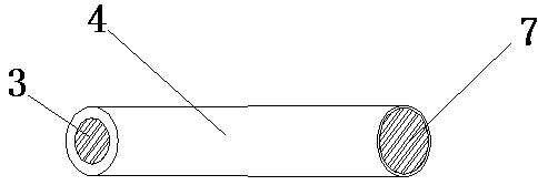
[0032] The frame 3 and the test piece disk 7 are connected by a cantilever type telescopic component; the cantilever type telescopic component can adjust the distance between the frame 3 and the test piece disk 7 through expansion, and the cantilever type telescopic component and the machine The frame 3 and the test piece disk 7 are rotatably connected, and a base 10 is also provided directly under the test piece disk 7, and the test piece disk 7 is suspended above the base 10 under the support of a cantilever telescopic assembly. A positioning device is also arranged between 7 and the base.
Embodiment 2
[0034] The structure of Embodiment 2 is the same as that of Embodiment 1, the difference lies in:
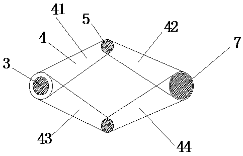
[0035] Such as Figure 2-3 As shown: the cantilever telescopic assembly includes four equal lengths of a first arm 41, a second arm 42, a third arm 43, and a fourth arm 44, the first arm 41 and the second arm One end of the arm 42, the third arm 43 and the fourth arm 44 is hinged through the rotating shaft 5, the other end of the first arm 41, the third arm 43 is rotatably connected to the frame, and a snap ring 11 is provided at the rotating connection. .
[0036] The other ends of the second arm 42 and the fourth arm 44 are rotatably connected with the bottom of the test piece disk 7, and a fixed ring 12 is provided at the bottom rotative connection.
[0037] The test piece disc is in the shape of an inverted T, and includes an upper disc body 71 and a cylindrical lower connecting column 72. Bearings are arranged between the second and fourth support arms 42 and 44 and the lower co...
Embodiment 3
[0040] The structure of Embodiment 3 is the same as that of Embodiment 2, the difference lies in:
[0041] Such as Figure 4 As shown, the positioning device is a bottoming bolt 8. The bottoming bolt 8 includes a hemispherical end, a plurality of through holes are arranged at intervals on the edge of the test piece disk, and the upper surface of the base is evenly densely covered with hemispherical grooves 9. The bottoming bolt 8 passes through the through hole, and the hemispherical end of the bottoming bolt 8 is clamped in the hemispherical groove 9 of the base to position the test piece plate.
[0042] There are 3 bottom bolts 8 evenly arranged along the edge of the test piece disk, and the top surface of the test piece disk 7 is also provided with a bubble level.
PUM
 Abstract
Description
Claims
Application Information
 - R&D
- Intellectual Property
- Life Sciences
- Materials
- Tech Scout
- Unparalleled Data Quality
- Higher Quality Content
- 60% Fewer Hallucinations
Browse by: Latest US Patents, China's latest patents, Technical Efficacy Thesaurus, Application Domain, Technology Topic, Popular Technical Reports.
© 2025 PatSnap. All rights reserved.Legal|Privacy policy|Modern Slavery Act Transparency Statement|Sitemap|About US| Contact US: help@patsnap.com


