Concave grating-based cuboid portable Raman spectrometer

A Raman spectrometer and concave grating technology, applied in the field of Raman spectroscopy, can solve the problems of large volume, large space, and irregular appearance of the outer shell, and achieve the effect of reducing the overall volume and shortening the installation distance

Pending Publication Date: 2017-06-13
NCS TESTING TECH
View PDF7 Cites 3 Cited by
  • Summary
  • Abstract
  • Description
  • Claims
  • Application Information

AI Technical Summary

Problems solved by technology

[0002] With the development of spectrometer technology, portable Raman spectrometers are more and more widely used. At present, inside the portable Raman spectrometer based on concave grating, the Raman scattering signal generated by the sample to be measured is excited by laser, and enters the spectrometer through the slit. After the diffraction and splitting of the concave grating, it is focused on the detector to form a Raman spectrum. Due to the optical structure characteristics of the concave grating, the spatial distance and relative angle between the slit and the detector and the concave grating along the optical path are fixed values. The grating portable Raman spectrometer is used for fixed installation of slits, concave gratings, detectors and other equipment. The polygonal design easily leads to the large volume of the outer shell used to cover the spectrometer, and the appearance shape is not regular enough. The space formed between the outer shell and the shell bracket is too large, which is not conducive to holding with one hand, which leads to the loss of the spectrometer. Not convenient enough to carry and use

Method used


Image

  • Concave grating-based cuboid portable Raman spectrometer

Examples


Embodiment Construction

[0016] Specific embodiments of the present invention will be described in detail below in conjunction with the accompanying drawings.

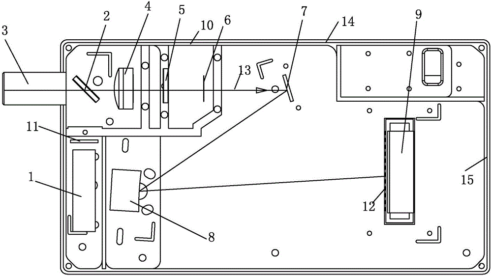
[0017] Such as figure 1 As shown, the cuboid portable Raman spectrometer based on the concave grating in the present invention includes a housing bracket 10 for fixedly installing various components, and a laser 1, a 45-degree angle edge filter 2, and a lens are fixedly installed in the housing bracket 10 3. Concentrating lens 4, edge filter 5, slit 6, mirror 7, concave grating 8 and detector 9, wherein:

[0018] Lens 3 is fixedly installed on the side wall of housing support 10, 45 degree angle edge filter 2, condenser lens 4, slit 6 are fixed in the housing support 10 in sequence, and lens 3, 45 degree angle edge filter The center points of the light sheet 2, the condenser lens 4, and the slit 6 are located on the same straight line 13;

[0019] On the straight line 13 and at the rear side of the slit 6, a reflector 7 for changing the tran...


PUM


Abstract

The invention discloses a concave grating-based cuboid portable Raman spectrometer. The concave grating-based cuboid portable Raman spectrometer comprises a casing bracket, a lens fixedly mounted on the side wall of the casing bracket, a 45-degree edge filter, a condensing lens and a gap, a reflector and a detector, wherein the 45-degree edge filter, the condensing lens and the gap are mounted on the central line of the lens in sequence; the reflector is arranged on a straight line where the central line of the lens is located, is fixedly mounted on the rear side of the gap and is used for changing the transmitting direction of a Raman signal penetrating through the gap and reaching a concave grating; a detector is fixedly mounted on the side edge of the reflector, the long edge of the detector is perpendicular to the straight line, and a perpendicular point, which is perpendicular to the straight line, on the long edge of the detector is located on the back surface of the reflector; the concave grating is fixedly mounted in the face of the detector and is used for receiving the Raman signal reflected by the reflector. According to the concave grating-based cuboid portable Raman spectrometer, by addition of the reflector, a light path is deflected; incident light of the spectrometer with the straight line and the long edge of the detector are in a perpendicular relation, and the light path is folded, so that a limited spectrometer space is effectively used, and the spectrometer is of a regular and compact quadrilateral structure.

Description

technical field [0001] The present invention relates to a kind of Raman spectroscopic technology, more specifically, relates to a cuboid portable Raman spectrometer based on a concave grating. Background technique [0002] With the development of spectrometer technology, portable Raman spectrometers are more and more widely used. At present, inside the portable Raman spectrometer based on concave grating, the Raman scattering signal generated by the sample to be measured is excited by laser, and enters the spectrometer through the slit. After the diffraction and splitting of the concave grating, it is focused on the detector to form a Raman spectrum. Due to the optical structure characteristics of the concave grating, the spatial distance and relative angle between the slit and the detector and the concave grating along the optical path are fixed values. The grating portable Raman spectrometer is used for fixed installation of slits, concave gratings, detectors and other equ...

Claims


Application Information

Patent Timeline
Patent Type & Authority Applications(China)
IPC IPC(8): G01N21/65G01N21/01
CPCG01N21/01G01N21/65G01N2201/06113G01N2201/0221G01N2021/0112G01N2021/655
Inventor 江洋周泽锋孔祥宏史宏伟仝琳琳崔飞鹏
Owner NCS TESTING TECH
Why Eureka
Try Eureka