Electric power collector and energy consumption monitoring method thereof

A technology of power collection and wires, which is applied in the field of energy consumption monitoring, can solve problems such as adverse effects of construction operations, affecting construction progress, and slowing down construction progress, so as to save the wiring and debugging process, facilitate the installation of equipment, and reduce the installation space Effect

Active Publication Date: 2017-06-13
NANJING TIANSU AUTOMATION CONTROL SYST
View PDF7 Cites 11 Cited by
  • Summary
  • Abstract
  • Description
  • Claims
  • Application Information

AI Technical Summary

Problems solved by technology

However, in actual project construction, it is difficult for the owner to cut power, especially in some special occasions, such as laboratories, hospitals, airports, etc., which require 24-hour uninterrupted power supply, which will seriously affect the construction progress. increase construction cost
In addition, the volume of traditional monitoring equipment is relatively large, and the space in the substation, box-type transformer, and user station meter box is relatively small, which will adversely affect the construction operation during the energy-saving transformation process
Most of the current energy consumption monitoring equipment is a wired network, and communication cables need to be laid during the construction process, which also slows down the construction progress and increases the cost

Method used


Image

  • Electric power collector and energy consumption monitoring method thereof
  • Electric power collector and energy consumption monitoring method thereof
  • Electric power collector and energy consumption monitoring method thereof

Examples


Embodiment Construction

[0041] In order to better understand the technical content of the present invention, specific embodiments are given together with the attached drawings for description as follows.

[0042] Aspects of the invention are described in this disclosure with reference to the accompanying drawings, which show a number of illustrated embodiments. Embodiments of the present disclosure are not necessarily intended to include all aspects of the invention. It should be appreciated that the various concepts and embodiments described above, as well as those described in more detail below, can be implemented in any of numerous ways, since the concepts and embodiments disclosed herein are not limited to any implementation. In addition, some aspects of the present disclosure may be used alone or in any suitable combination with other aspects of the present disclosure.

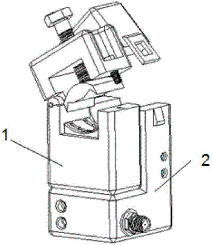
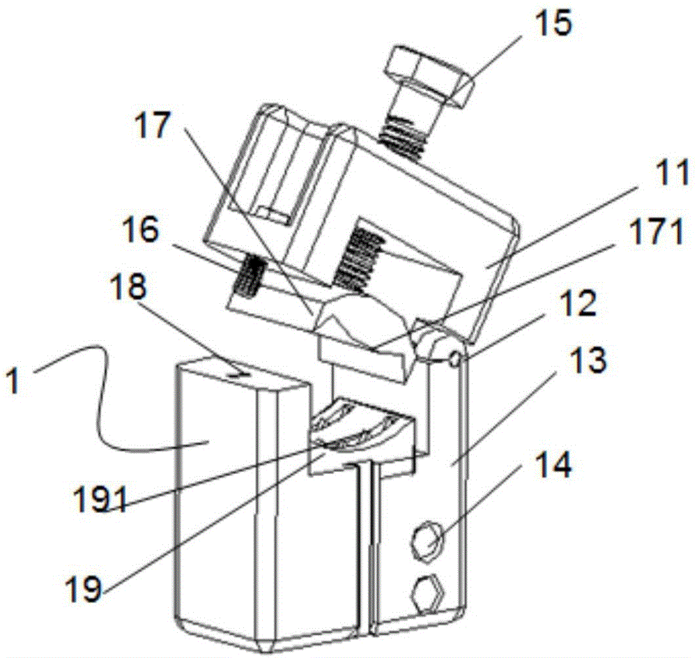
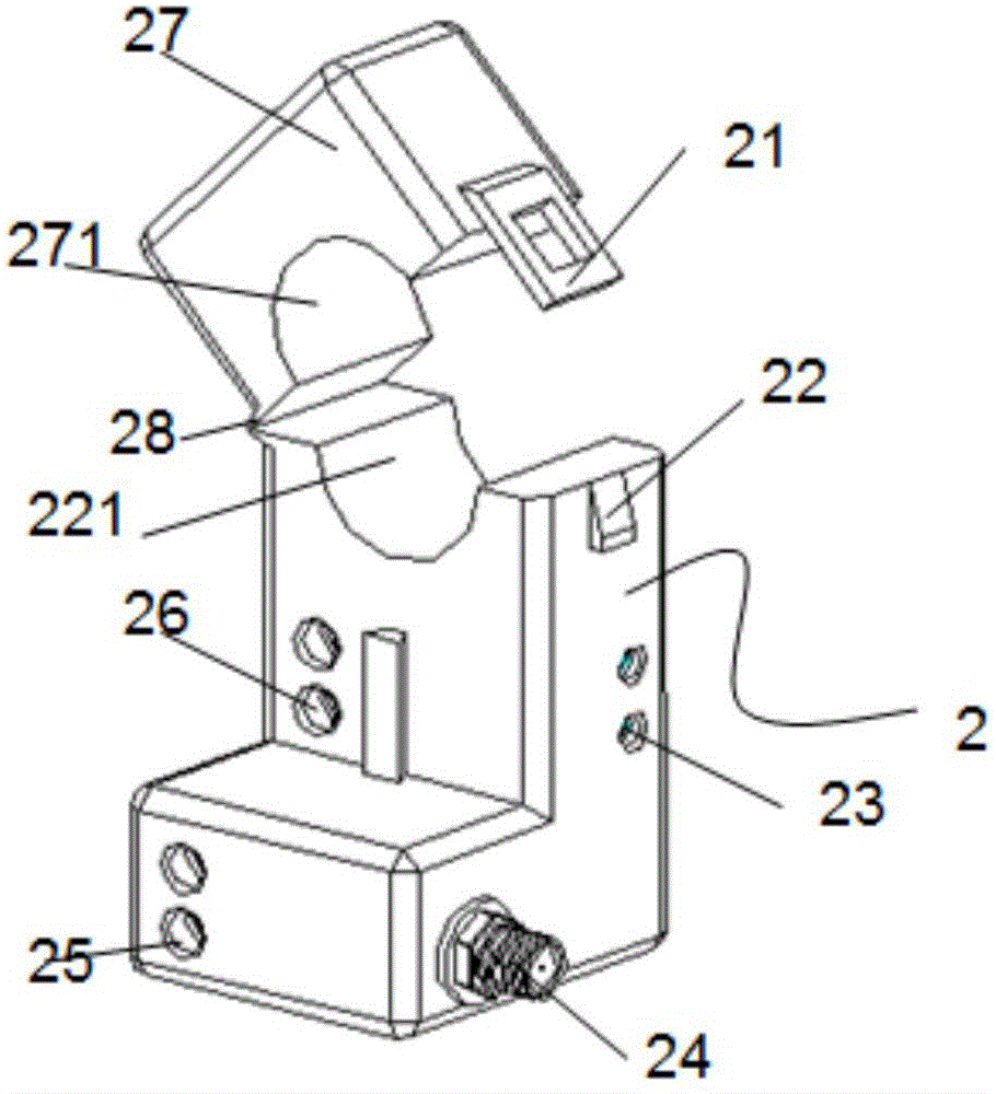
[0043] Such as figure 1 As shown, according to some embodiments of the present invention, a power collector includes a punc...


PUM


Abstract

The invention provides an electric power collector. The collector comprises a piercing power taking module and M open mutual inductor modules, wherein M is a positive integer larger than or equal to 1. The piercing power taking module is used for extracting voltage signals of a cable and is installed on a main line of a wire. The piercing power taking module is provided with a voltage output wiring terminal. The open mutual inductor modules are installed on branch lines needing signal acquisition and are provided with ground wire wiring ports and voltage input wiring terminals, wherein the ground wire wiring ports are connected with a ground wire through wires, and the voltage input wiring terminals are connected with the voltage output wiring terminal of the piercing power taking module through wires. The open mutual inductor modules are used for acquiring current signals of the measured branch lines, processing the acquired current and voltage signals and then outputting the processed current and voltage signals to an electric quantity monitoring end through communication modules arranged on the open mutual inductor modules. Electric energy monitoring can be conducted on electric equipment without power outage; besides, the electric power collector is simple in structure and can adapt to complex spot transformation environments.

Description

technical field [0001] The invention relates to the field of energy consumption monitoring, in particular to a power collector capable of completing energy consumption monitoring of end user power lines without power failure and an energy consumption monitoring method thereof. Background technique [0002] With the country's emphasis on energy conservation and emission reduction, all end users urgently need to monitor energy consumption to provide data support for emission reduction. However, in some special occasions, it is very difficult to carry out power outage reconstruction, and it is necessary to coordinate the needs of all parties, which has a great impact on the construction schedule and cost control. Therefore, a kind of energy-saving transformation method without power failure is imminent. [0003] The current transformer in the traditional system consists of a primary transformer and a secondary transformer (generally called an instrument transformer, which is i...

Claims


Application Information

Patent Timeline
Patent Type & Authority Applications(China)
IPC IPC(8): G01R15/00G01R11/04
CPCG01R11/04G01R15/00Y02T10/70
Inventor 夏国平刘志明蔡嘉楠杨毅马如明王伟江
Owner NANJING TIANSU AUTOMATION CONTROL SYST
Why Eureka
Try Eureka