Active optical cable connector and active optical cable assembly using same

A fiber optic cable connector and connector technology, which is applied in the coupling of optical components, optical waveguides, light guides, etc., can solve problems such as impact and collision, affect connector reliability, and cannot be disassembled and repaired, so as to improve reliability and avoid shock The effect of collision

Active Publication Date: 2017-06-13
CHINA AVIATION OPTICAL-ELECTRICAL TECH CO LTD
View PDF5 Cites 2 Cited by
  • Summary
  • Abstract
  • Description
  • Claims
  • Application Information

AI Technical Summary

Problems solved by technology

[0002] The active optical cable assembly includes an active optical cable and an active optical cable connector arranged at both ends of the active optical cable. The active optical cable connector includes a connector housing and a photoelectric conversion unit installed in the connector housing. For example, the application publication number is CN104330857 A, an active optical cable connector disclosed in a Chinese patent application with an application publication date of 2015.02.04. The front end of the active optical cable connector is an electric plug, and the connector housing and the plug housing constitute the connector housing of the connector Body assembly, the connector housing is rotated and equipped with a connecting nut, and the connecting nut connects the electrical plug housing and the connector housing together by cooperating with the external thread on the outer circumference of the rear end of the electrical plug housing, and the photoelectric conversion uni...

Method used


Image

  • Active optical cable connector and active optical cable assembly using same
  • Active optical cable connector and active optical cable assembly using same
  • Active optical cable connector and active optical cable assembly using same

Examples


Embodiment Construction

[0038] Embodiments of the present invention will be further described below in conjunction with the accompanying drawings.

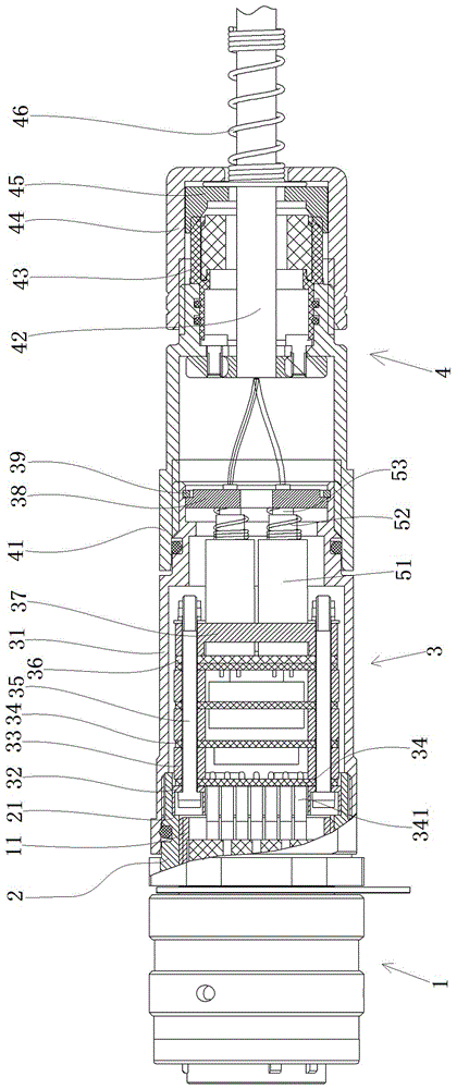
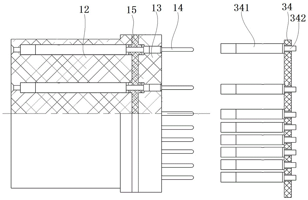
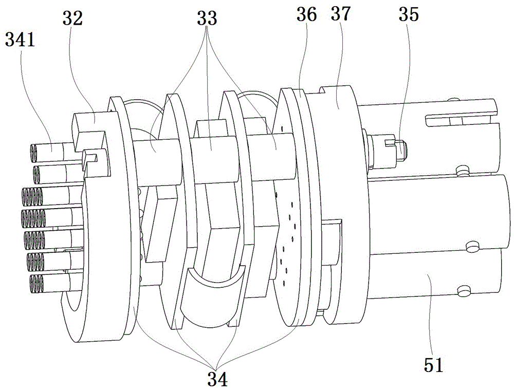
[0039] Specific embodiments of the active optical cable assembly of the present invention, such as Figure 1 to Figure 4As shown, the active optical cable assembly includes an active optical cable and an active optical cable connector arranged at both ends of the active optical cable. The front part of the connector is the electrical plug 1 for the adaptive connection of the active optical cable connector, the rear part of the connector 3 is used to install and accommodate the photoelectric conversion unit, and the tail part 4 is used to fix the optical cable and has a waterproof sealing function.

[0040] The electric plug 1 includes an electric plug housing 11 extending along the front-to-back direction, and an external thread is provided on the outer periphery of the rear end of the electric plug housing 11 . The rear part 3 of the connector is the c...


PUM


Abstract

The invention relates to an active optical cable connector and an active optical cable assembly using the same. The active optical cable connector comprises a connector shell assembly and a photoelectric conversion unit arranged in an inner cavity of the connector shell assembly, wherein a stop structure is arranged in the inner cavity of the connector shell assembly in front of the photoelectric conversion unit; a pressing structure for elastically pressing the photoelectric conversion unit against the stop structure is arranged in the inner cavity of the connector shell assembly behind the photoelectric conversion unit; and the photoelectric conversion unit is elastically pressed in the inner cavity of the connector shell assembly by the pressing structure. According to the connector, the problem that the photoelectric conversion unit cannot be dismantled due to use of mucilage glue is solved; and the photoelectric conversion unit is elastically pressed, and elastic floating force can be provided when the connector is vibrated and the photoelectric conversion unit moves in the inner cavity of the connector shell assembly, so that impact and collision of the photoelectric conversion unit and the connector shell assembly are avoided and the reliability of the connector is improved.

Description

technical field [0001] The invention relates to an active optical cable connector and an active optical cable assembly using the active optical cable connector. Background technique [0002] The active optical cable assembly includes an active optical cable and an active optical cable connector arranged at both ends of the active optical cable. The active optical cable connector includes a connector housing and a photoelectric conversion unit installed in the connector housing. For example, the application publication number is CN104330857 A, an active optical cable connector disclosed in a Chinese patent application with an application publication date of 2015.02.04. The front end of the active optical cable connector is an electric plug, and the connector housing and the plug housing constitute the connector housing of the connector Body assembly, the connector housing is rotated and equipped with a connecting nut, and the connecting nut connects the electrical plug housin...

Claims


Application Information

Patent Timeline
IPC IPC(8): G02B6/42
CPCG02B6/4201G02B6/4256G02B6/428G02B6/4284G02B6/4285
Inventor 周超黄剑峰朱正红
Owner CHINA AVIATION OPTICAL-ELECTRICAL TECH CO LTD
Why Eureka
Try Eureka