
Mechanism kinematic pair wear simulation method based on mesh deformation technology

A technology of mechanism motion and simulation methods, applied in design optimization/simulation, special data processing applications, instruments, etc., can solve the problems of complex surface wear mechanism of parts, technical difficulty of theoretical research and experimental research, and scrap of parts.

Active Publication Date: 2017-06-13
NANJING YUEBOO POWER SYST CO LTD
View PDF7 Cites 6 Cited by
  • Summary
  • Abstract
  • Description
  • Claims
  • Application Information

AI Technical Summary

Problems solved by technology

Most of the parts have static or dynamic contact and cooperation with other parts. When the load acts on the surface, friction and wear occur. When the wear accumulates to a certain extent, the dimensional changes of the parts exceed the allowable range and the parts are scrapped.
Component life is largely limited by surface wear
[0003] The wear mechanism of the surface of parts is very complicated, which is not only related to the material properties of the parts themselves, but also closely related to the interaction between parts. At present, the theoretical research and experimental research on the surface wear of parts have high technical difficulties.

Method used


Image

  • Mechanism kinematic pair wear simulation method based on mesh deformation technology
  • Mechanism kinematic pair wear simulation method based on mesh deformation technology
  • Mechanism kinematic pair wear simulation method based on mesh deformation technology

Examples


Embodiment Construction

[0039] The technical solutions of the present invention will be clearly and completely described below in conjunction with the accompanying drawings of the present invention.

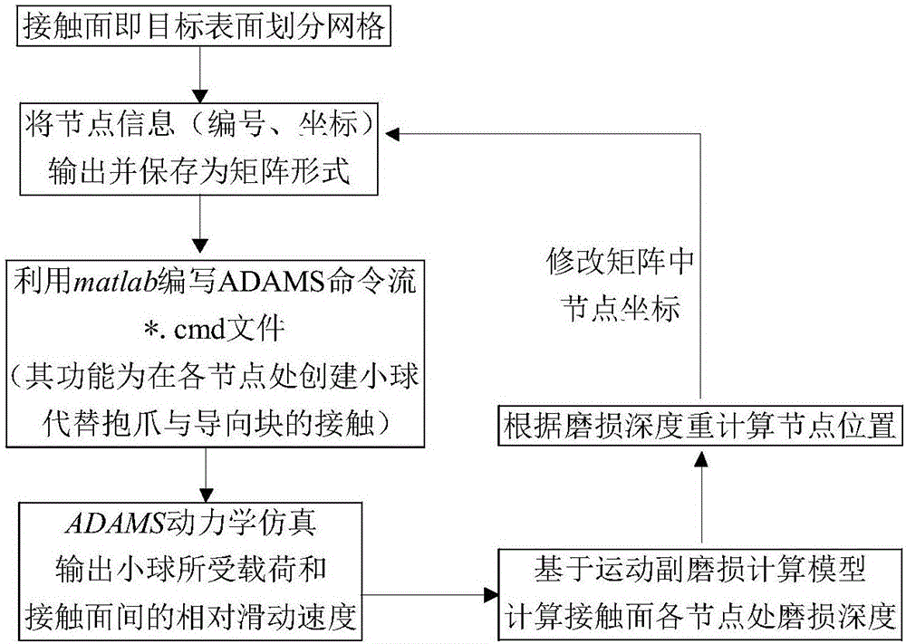
[0040] Such as image 3 As shown, a method for simulating wear of a mechanism kinematic pair based on mesh deformation technology described in an embodiment of the present invention includes the following steps:

[0041] 1) Create a mechanism kinematic pair model, judge the contact area of ​​the mechanism kinematic pair model, record it as the target area, use grids to divide the target area, and output the numbering and original coordinates of the grid nodes;

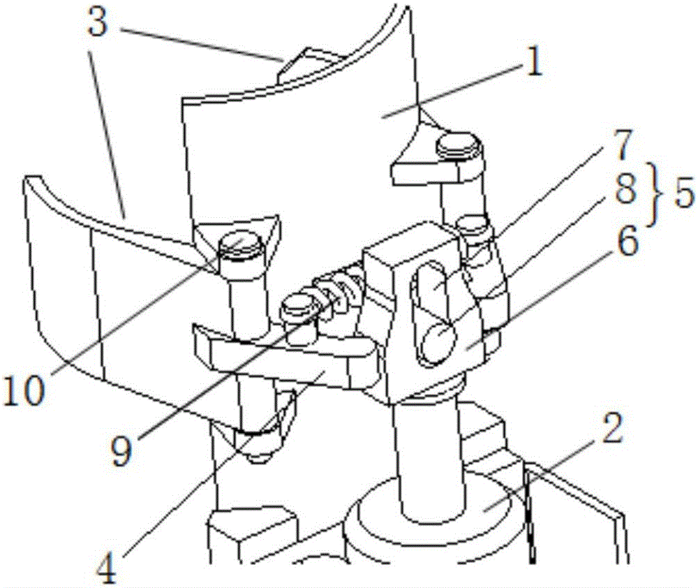
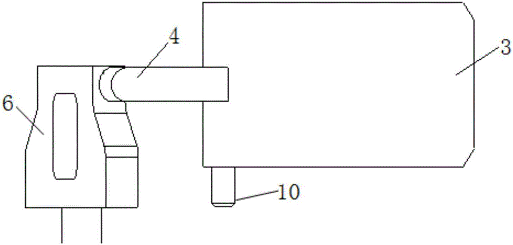
[0042] In this example, if Figure 1-2 As shown, the kinematic pair model of the mechanism includes a bracket model 1, an electromagnet model 2, two claw models 3, two connecting arm models 4 and a guide block model 5, and the two claw models 3 pass through the pin model 10 are symmetrically arranged at both lateral ends of the bracket model 1...


PUM

PropertyMeasurementUnit
Radiusaaaaaaaaaa

Abstract

The invention relates to a mechanism kinematic pair wear simulation method based on the mesh deformation technology. The method includes the following steps that a mechanism kinematic pair model is created, a contact region of the mechanism kinematic pair model is judged to be recorded as a target region, mesh generation is conducted on the target region, and the serial number and initial coordinate of a grid node are output; a massless small ball model is created at the grid node, the small ball model takes the place of the target region to make contact with the mechanism kinematic pair model, dynamical simulation is conducted, and the interaction force and relative sliding velocity between the small ball model and the mechanism kinematic pair model are obtained; according to the Achard wear calculation formula, the wearing depth at the grid node is calculated; according to the wearing depth, a new coordinate of the grid node is calculated. By a mesh generation means, the target region is discrete, the quantitative relationship among contact pressure, the kinematic pair inter-element relative sliding velocity and a wear extent is built, and by visually presenting the post-wear characteristics of the target region, a reference is provided for structure design.

Description

technical field [0001] The invention relates to the technical field of mechanical structure simulation design, in particular to a method for simulating wear of mechanism kinematic pairs based on grid deformation technology. Background technique [0002] One of the main failure modes of mechanical products is the surface wear of parts. Most of the parts have static or dynamic contact and cooperation with other parts. When the load acts on the surface, friction and wear occur. When the wear accumulates to a certain extent, the dimensional changes of the parts exceed the allowable range and the parts are scrapped. The service life of parts is largely limited by surface wear. [0003] The wear mechanism of the surface of parts is very complex, not only related to the material properties of the parts themselves, but also closely related to the interaction between parts. At present, the theoretical research and experimental research on the surface wear of parts have high technica...

Claims


Application Information

Patent Timeline
IPC IPC(8): G06F17/50
CPCG06F30/13G06F30/20
Inventor 李占江高超赵志专陈元钊
Owner NANJING YUEBOO POWER SYST CO LTD
Learn More