
Heavy-current wire distributing, power taking and current shunting device

A technology of electrical shunting and high current, which is applied in the direction of needle point/slotted plate contacts used for penetrating insulated wires/cable core wires, etc., which can solve the problems of poor power extraction efficiency, poor stability of electricity extraction, and inapplicability, and achieve Easy installation, high efficiency and stability, avoiding the effect of easy damage

Pending Publication Date: 2017-06-13
浙江捷莱光电科技有限公司
View PDF11 Cites 1 Cited by
  • Summary
  • Abstract
  • Description
  • Claims
  • Application Information

AI Technical Summary

Problems solved by technology

Although this structure adopts the method of puncturing to obtain power, the structure of the power-taking screw is too simple, and the power-taking efficiency and stability of power-taking are poor, so it cannot be applied to occasions where multiple string lights need to use high-current wiring

Method used


Image

  • Heavy-current wire distributing, power taking and current shunting device
  • Heavy-current wire distributing, power taking and current shunting device
  • Heavy-current wire distributing, power taking and current shunting device

Examples


Embodiment

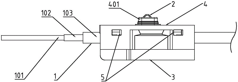
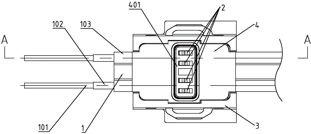
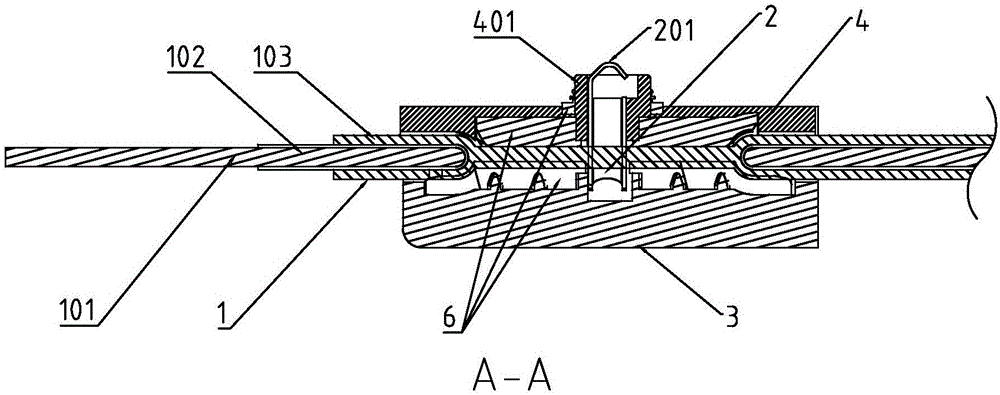
[0026] Such as figure 1 with figure 2 The shown large-current wiring power-taking and shunting device includes a cable line 1, a puncture needle 2, a base 3, and an upper cover 4 matched with the base. The upper cover and the base are respectively located above and below the cable, and the puncture needle is covered by the upper cover. The top of the cable passes through the upper cover and the cable and contacts the base.

[0027] The cable is a flat cable with a dumbbell-shaped cross-section, and the core 101 of the cable is arranged in parallel at the end of the dumbbell-shaped cross-section. The cable includes two rows of parallel cores 101, an insulating layer 102 and an anti-aging protective layer 103 wrapped in the outermost layer. The insulating layer is arranged on the outer surface of the core. The core is from 0.2mm-0.5 in diameter. A copper cable formed by twisting multiple strands of thin copper wires with a thickness of 1 mm, the surface of the core is provided wit...


PUM


Abstract

The invention relates to an auxiliary device for an illuminating lamp, and particularly relates to a heavy-current wire distributing, power taking and current shunting device. The heavy-current wire distributing, power taking and current shunting device comprises a cable wire, puncture needles, a base and an upper cover, wherein the upper cover cooperates with the base; the upper cover and the base are located above and below the cable wire respectively; the puncture needles penetrate through the upper cover and the cable wire from the top of the upper cover and are in contact with the base; the cable wire is a flat cable wire with a dumbbell-shaped cross section; wire cores of the cable wire are arranged at the end part of the dumbbell-shaped cross section in parallel; the puncture needles are rectangular parallelepipeds with cross sections in rectangular-ambulatory-plane shapes; the lower parts of the puncture needles are provided with openings cooperating with the wire cores of the cable wire; the top of the base is provided with a groove cooperating with the upper cover; the side surface, which intersects with the cable wire, of the base is provided with an open hole matched with the outer contour of the cross section of the cable wire; the top of the upper cover is provided with a bulge; the top of the bulge is provided with open holes through which the tops of the puncture needles are exposed.

Description

Technical field [0001] The invention relates to an auxiliary device of a lighting lamp, in particular to a high-current wiring power-taking shunt device. Background technique [0002] Outdoor lighting is a luminaire for outdoor use. With today’s road lighting development requirements, it must develop in terms of high efficiency, energy saving, low carbon, and green environmental protection. The energy consumed by road lighting every year accounts for the entire energy consumption. A large proportion, how to make road lighting products conform to the general trend of international development is the research direction of all scientific and technological personnel in the lighting field. The current outdoor lighting equipment consumes a lot of energy. In order to save energy, LED outdoor bar-shaped luminaires are currently used more frequently. Due to the characteristics of heat dissipation, waterproof and dustproof, the shell is generally made of aluminum or aluminum alloy plus tem...

Claims


Application Information

Patent Timeline
Patent Type & Authority Applications(China)
IPC IPC(8): H01R4/24
CPCH01R4/24
Inventor 戴军历莫忠堂
Owner 浙江捷莱光电科技有限公司
Learn More