Transformer circuit and method for lowering no-load power consumption

A transformer circuit and transformer technology, applied in the electronic field, can solve problems such as increased voltage drop, increased no-load power consumption, and increased

Active Publication Date: 2017-06-13
TCL CHINA STAR OPTOELECTRONICS TECH CO LTD
View PDF3 Cites 4 Cited by
  • Summary
  • Abstract
  • Description
  • Claims
  • Application Information

AI Technical Summary

Problems solved by technology

However, when the Zener diode is set, if the output voltage of the secondary winding of the transformer becomes higher, the output voltage of the corresponding auxiliary winding will also rise, and the input voltage of the auxiliary winding circuit will rise. Due to the setting of the Zener diode, The output voltage of the auxiliary winding circuit remains a

Method used


Image

  • Transformer circuit and method for lowering no-load power consumption
  • Transformer circuit and method for lowering no-load power consumption
  • Transformer circuit and method for lowering no-load power consumption

Examples


Embodiment Construction

[0017] Embodiments of the present invention will be described below in conjunction with the accompanying drawings.

[0018] The invention discloses a transformer circuit and a method for reducing no-load power consumption, which can reduce the voltage drop on components of the auxiliary winding when the output voltage of the auxiliary winding is high, thereby reducing the no-load power consumption. Each will be described in detail below.

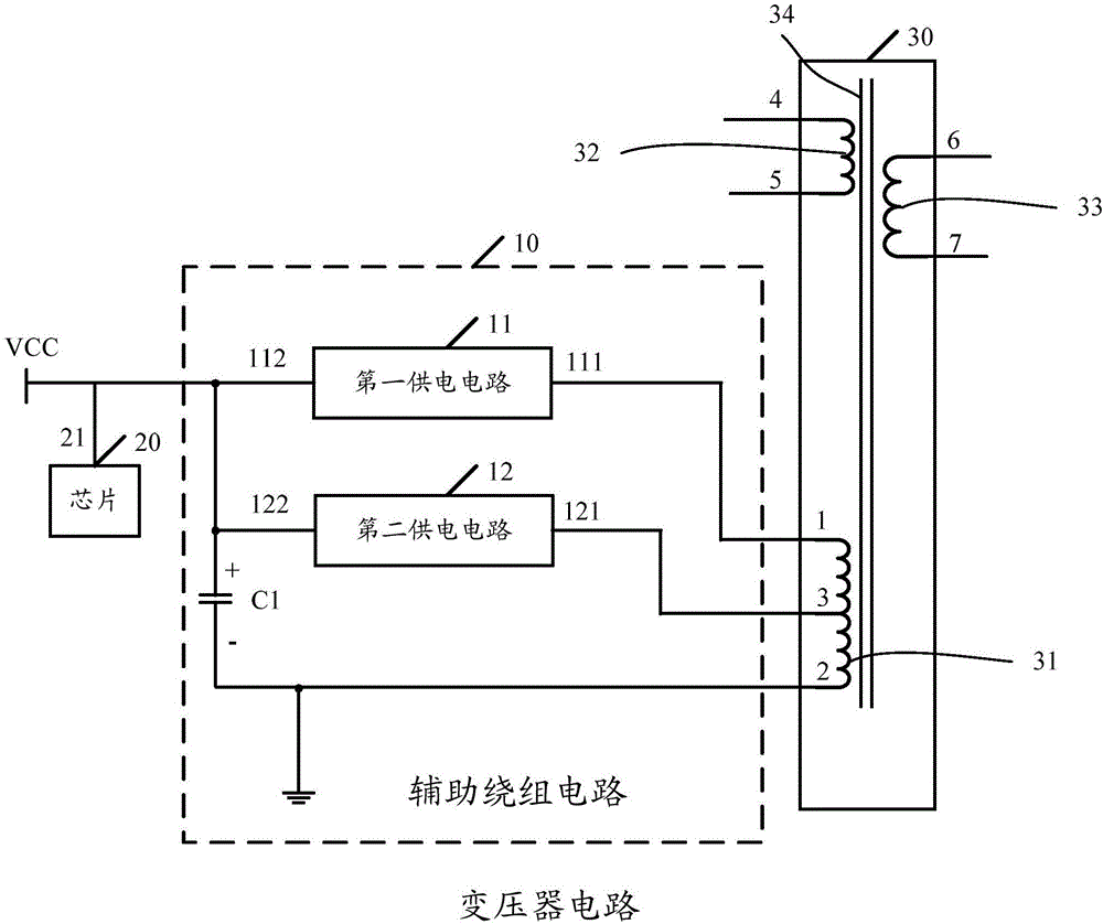
[0019] see figure 1 , figure 1 It is a structural schematic diagram of a transformer circuit disclosed by the present invention. like figure 1 As shown, the transformer circuit includes a transformer 30 and an auxiliary winding circuit 10. The auxiliary winding circuit 10 is used to supply power to the chip 20. The transformer 30 includes an iron core 34, a primary winding 32, a secondary winding 33 and an auxiliary winding 31. The auxiliary winding circuit 10 Connect the auxiliary winding 31 of the transformer 30. The auxiliary winding ...


PUM


Abstract

The invention discloses a transformer circuit and a method for lowering no-load power consumption. The transformer circuit comprises a transformer and an auxiliary winding circuit. The transformer comprises an iron core, a primary winding, a secondary winding and an auxiliary winding. The auxiliary winding circuit is connected with the auxiliary winding. The auxiliary winding circuit supplies power to a chip. The auxiliary winding circuit comprises a first power supply circuit and a second power supply circuit. The auxiliary winding comprises a first end, a second end and a tap located between the first end and the second end, the first end of the auxiliary winding is connected with the input end of the first power supply circuit, the tap of the auxiliary winding is connected with the input end of the second power supply circuit, the output end of the first power supply circuit is connected with the output end of the second power supply circuit and the power supply end of the chip, and the second end of the auxiliary winding is grounded; input voltage of the second power supply circuit is smaller than input voltage of the first power supply circuit. The no-load power consumption can be lowered when the voltage output by the whole auxiliary winding becomes larger.

Description

technical field [0001] The invention relates to the field of electronic technology, in particular to a transformer circuit and a method for reducing no-load power consumption. Background technique [0002] In order to meet the requirements of wide voltage output in the current transformer, the voltage of the secondary winding of the transformer often changes within a relatively large range. For a transformer with an auxiliary winding, since the output voltage of the auxiliary winding is proportional to the voltage of the secondary winding of the transformer, when the output voltage of the transformer is low, the voltage coupled to the auxiliary winding is also low, and the output of the auxiliary winding The voltage is lower. The auxiliary winding generally supplies power to the chip through the auxiliary winding circuit, and semiconductor devices such as diodes and triodes are usually arranged in the auxiliary winding circuit. When the output voltage of the auxiliary wind...

Claims


Application Information

Patent Timeline
IPC IPC(8): H02J9/06H02M3/335H01F27/38H01F29/00
CPCH01F27/38H01F29/00H02M3/335H02M1/0006H02M1/0032Y02B70/10H01F27/29H01F27/341H01F29/025H02M5/12
Inventor 李文东
Owner TCL CHINA STAR OPTOELECTRONICS TECH CO LTD
Why Eureka
Try Eureka