Forward-flyback auxiliary power supply circuit and forward-flyback power supply circuit

A technology of auxiliary power supply and power supply circuit, applied in the direction of high-efficiency power electronic conversion, electrical components, output power conversion devices, etc., can solve the problem of inability to achieve protection functions, and achieve consistency, obvious effect, and reduce no-load power. consumption effect

Active Publication Date: 2020-04-28
MORNSUN GUANGZHOU SCI & TECH
View PDF10 Cites 1 Cited by
  • Summary
  • Abstract
  • Description
  • Claims
  • Application Information

AI Technical Summary

Problems solved by technology

[0004] The power supply circuit of the flyback winding is simple, and the consistency of no-load power consumption can be guaranteed under high and low voltage. The disadvantage is that it cannot realize protection functions such as short circuit constant current.

Method used


Image

  • Forward-flyback auxiliary power supply circuit and forward-flyback power supply circuit
  • Forward-flyback auxiliary power supply circuit and forward-flyback power supply circuit
  • Forward-flyback auxiliary power supply circuit and forward-flyback power supply circuit

Examples


no. 1 example

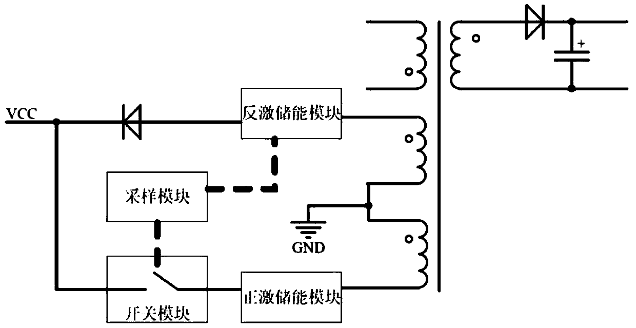
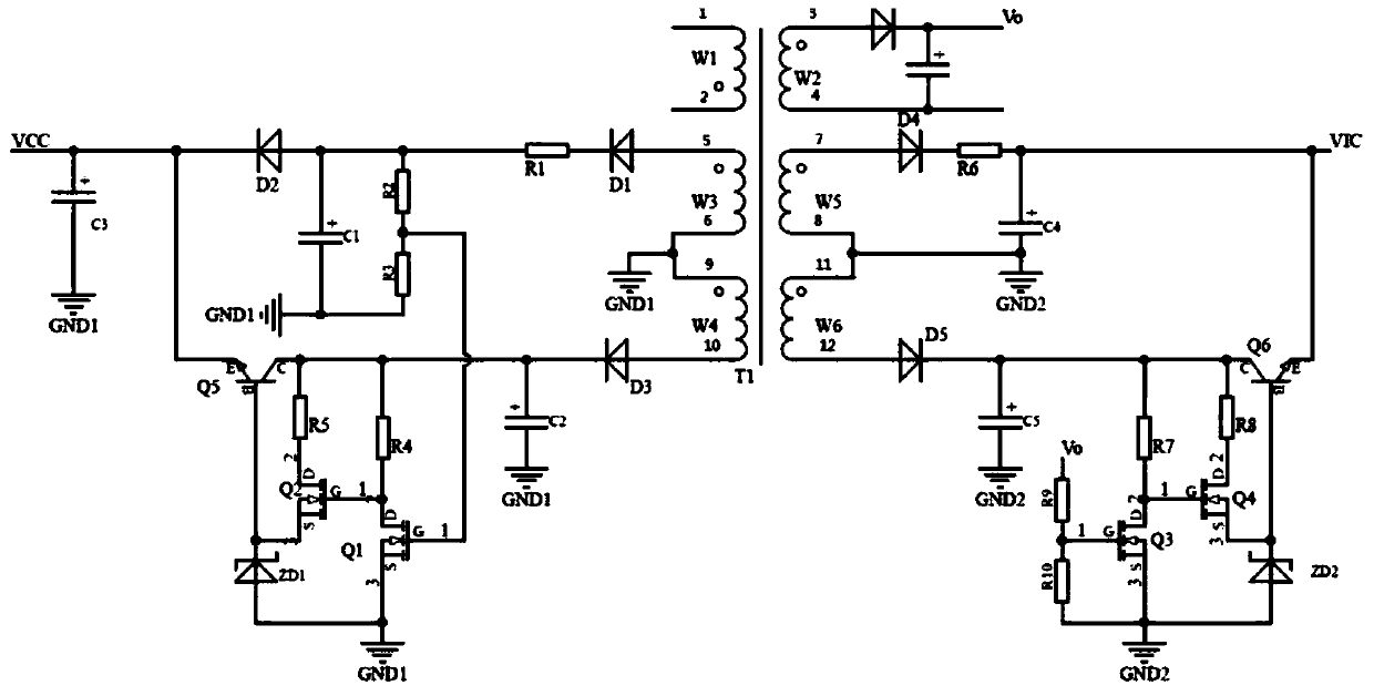
[0040] figure 2 It is the power supply circuit of the first embodiment of the present invention, including a flyback energy storage module, a forward energy storage module, a switch module, a sampling module, a first winding, a second winding, a diode, a capacitor C3 and a second flyback energy storage module, the second forward energy storage module, the second sampling module, the second switch module, the third winding, and the fourth winding.

[0041] The first winding and the second winding are arranged on the primary side of the switching power supply, one end of the first winding, one end of the second winding and one end of the primary winding of the switching power supply are terminals with the same name, and the other end of the first winding is connected to the second winding One end of the ground is grounded; the third winding and the fourth winding are set on the secondary side of the switching power supply, one end of the third winding, one end of the fourth win...

no. 2 example

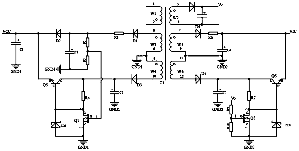
[0049] Such as image 3 The power supply circuit of the second embodiment of the present invention differs from the first embodiment in that the switch module and the second switch module have different configurations:

[0050] The switch module includes a transistor Q5 and a Zener diode ZD1, the emitter of the transistor Q5 is connected to the power supply VCC, the collector of the transistor Q5 is connected to the other end of the resistor R4, the base of the transistor Q5 is connected to the cathode of the Zener diode ZD1, and the MOS tube Q1 The drain and the anode of the Zener diode ZD1 are grounded.

[0051] The second switch module includes a transistor Q6, a Zener diode ZD2, the collector of the transistor Q6 is connected to one end of the resistor R7, the emitter of the transistor Q6 is connected to the voltage VIC, the base of the transistor Q6 is connected to the drain of the MOS transistor Q3, and the Zener diode The cathode of ZD2 and the anode of Zener diode ZD2...


PUM


Abstract

The invention discloses a forward-flyback auxiliary power supply circuit, which comprises a flyback power supply module, a forward power supply module and a sampling module, and can be applied to a KNX bus power supply and a circuit with a short-circuit constant current requirement or an extremely low voltage output requirement. According to the invention, when the power supply works in a steady state, the flyback power supply module supplies power to a main control IC and a feedback loop; the auxiliary power supply is switched to the forward power supply module to supply power to the main control IC and the feedback loop during a short circuit, and normal work of the IC and the feedback loop is guaranteed. The circuit can also realize a short-circuit constant-current function. The invention further discloses a forward-flyback power supply circuit, and the principle is the same as that of the forward-flyback auxiliary power supply circuit. According to the invention, low no-load powerconsumption and high complete machine efficiency under high and low voltage input are ensured.

Description

technical field [0001] The invention relates to the field of switching power supplies, in particular to a forward and flyback auxiliary power supply circuit and a forward and flyback power supply circuit. Background technique [0002] In the field of switching power supplies, the flyback topology and its extended topology are very popular and practical. The development of flyback topology is of great significance to product upgrades. [0003] In the design of switching power supply applications, the main control IC is generally powered by the auxiliary winding, and the auxiliary power supply circuit usually uses a flyback winding power supply circuit or a forward winding power supply circuit. [0004] The power supply circuit of the flyback winding is simple, and the consistency of no-load power consumption can be guaranteed under high and low voltage. The disadvantage is that it cannot realize protection functions such as short circuit constant current. The forward windin...

Claims


Application Information

Patent Timeline
Patent Type & Authority Applications(China)
IPC IPC(8): H02M1/00
CPCH02M1/00H02M1/0006H02M1/0032H02M1/0048Y02B70/10
Inventor 潘桂凯罗皓宋建峰
Owner MORNSUN GUANGZHOU SCI & TECH
Why Eureka
Try Eureka