A 0°~360° digital phase shift control method and system

A technology of digital phase shifting and control method, which is applied in the control/regulation system, the conversion device of output power, the conversion of DC power input to DC power output, etc. Adjustment and other problems to achieve the effect of smooth adjustment process, high adjustment accuracy and high adjustment accuracy

Active Publication Date: 2019-03-19
NARI TECH CO LTD +4
View PDF4 Cites 0 Cited by
  • Summary
  • Abstract
  • Description
  • Claims
  • Application Information

AI Technical Summary

Problems solved by technology

[0005] Aiming at the problem that most of the current phase shift control algorithms can only realize phase shift within the range of 0°~180°, and the duty cycle cannot be adjusted arbitrarily, or it is difficult to realize the adjustment of the duty cycle, the present invention proposes a 0°~360° °Digital phase shift control method and system, which can achieve very smooth switching at the 180° point and 360° point where problems are prone to occur, and can also be very conveniently realized on the basis of phase shifting at any angle, arbitrarily changing the duty cycle, without affecting the generation of the dead zone

Method used


Image

  • A 0°~360° digital phase shift control method and system
  • A 0°~360° digital phase shift control method and system
  • A 0°~360° digital phase shift control method and system

Examples


Embodiment 1

[0044] A 0°~360° digital phase shift control method, comprising:

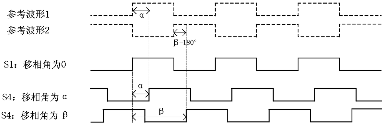
[0045] generating a pair of complementary first and second reference waves having the same duty cycle and frequency;

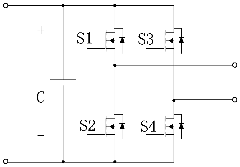
[0046] Select one of the bridge arms of the phase-shift control bridge circuit as the leading bridge arm, and the rest of the bridge arms as the lagging bridge arm;

[0047] Align the control signal of the switching tube on the leading bridge arm with the first reference wave, use the first reference wave or the second reference wave as the initial control signal of the switching tube on the lagging bridge arm, and perform an initial control signal on the lagging bridge arm Phase shifting, generating the control signals of all switching tubes on the lagging bridge arm, so that the lagging bridge arm lags behind the set phase shifting angle relative to the leading bridge arm, and the phase shifting angle ranges from 0° to 360°, thus completing the °Digital phase shift control.

[0048] In the ...

Embodiment 2

[0053] The difference between this embodiment and Embodiment 1 is that the 0°-360° digital phase shift control method also includes generating the required duty cycle, specifically including:

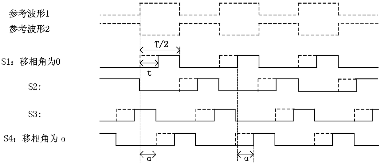
[0054] Set the initial duty cycle of the switching tube control signal to D, and the high level time to N

[0055] Judging the adjustment requirements of the duty cycle;

[0056] Phase-shift the rising edges of the control waves of all switching tubes on the leading bridge arm and the lagging bridge arm, so that the duty cycle of the newly generated control signal is (N±t) / T, and (N±t)

[0057] Specifically: (1) When it is judged that the duty cycle needs to be reduced, the rising edges of the control waves of all the switch tubes on the generated leading bridge arm and lagging bridge arm are phase-shifted backward, so that the newly generated control signal The duty cycle is (N-t) / T,...

Embodiment 3

[0061] The difference between this embodiment and Embodiment 1 is that the 0°-360° digital phase shift control method also includes generating the required dead zone, specifically including:

[0062] When only the dead zone needs to be generated, move the rising edges of the control waveforms of all switching tubes on the leading bridge arm and the lagging bridge arm backward by t dead , t dead dead In order to generate the phase-shifting time of the dead zone, T is the reference wave cycle.


PUM


Abstract

The invention discloses a 0-360 degree digital phase shift control method and system. A first reference wave and a second reference wave which are complementary to each other are generated, wherein the first reference wave and the second reference wave are same in duty cycle and frequency; one bridge arm of a phase controlled bridge circuit is selected and serves as a leading bridge arm, and the rest bridge arms serve as lagging bridge arms; a control signal of a switch pipe on the leading bridge arm is aligned with the first reference wave, the first reference wave or the second reference wave serves as an initial control signal of switch pipes on the lagging bridge arms, phase shifting is conducted on the initial control signal of lagging bridge arms, a control signal of all the switch pipes on the lagging bridge arms is generated, the lagging bridge arms are thus lagged by a set phase shift angle relative to the leading bridge arm, the phase shift range is 0-360 degrees, and therefore 0-360 degree digital phase shift is completed. According to the method and the system, very smooth switching can be achieved between a 180-degree point and a 360-degree point where problems are easy to occur, on the basis that phase shift at any angle can be very conveniently achieved, the duty cycle is changed at will, and generation of a dead zone is not affected.

Description

technical field [0001] The invention belongs to the technical field of power electronics, and in particular relates to a 0°-360° digital phase-shift control method and system. Background technique [0002] The traditional PWM control method achieves control by adjusting the pulse width. The switching method is hard switching. Due to the unavoidable parasitic parameters of the switching device and the devices connected to it, the voltage and current passing through the switching device are not pure square waves. Therefore, the power tube During the switching process, the voltage and current waveforms of the switching devices overlap, resulting in switching losses. And as the frequency increases, the proportion of switching loss in the total loss also increases proportionally. The phase-shift PWM control method realizes the change of the effective output pulse width by moving the phase-shift angle of the lagging bridge arm. The switching method is soft switching, which can be...

Claims


Application Information

Patent Timeline
Patent Type & Authority Patents(China)
IPC IPC(8): H02M3/157
CPCH02M3/157
Inventor 王志刚范镇淇侯凯王后生冯世宁刘建平徐建松辛甜梁帅奇王小红郑玉平
Owner NARI TECH CO LTD
Why Eureka
Try Eureka