Inertial Rotary Drive Device Based on Piezoelectric Fiber

A rotary drive device and piezoelectric fiber technology, applied in the direction of piezoelectric effect/electrostrictive or magnetostrictive motors, generators/motors, electrical components, etc., can solve large retraction motion, mechanism is not easy to control, Signals are not easy to generate and other problems, to achieve the effect of storing kinetic energy, overcoming difficult control, and reducing complexity

Inactive Publication Date: 2019-08-27
JILIN UNIV
View PDF8 Cites 0 Cited by
  • Summary
  • Abstract
  • Description
  • Claims
  • Application Information

AI Technical Summary

Problems solved by technology

Existing piezoelectric inertial drive devices mostly use asymmetrical electrical signals as excitation signals, but this drive device has disadvantages such as difficult signal generation, difficult mechanism control, and relatively large retraction motion.

Method used


Image

  • Inertial Rotary Drive Device Based on Piezoelectric Fiber
  • Inertial Rotary Drive Device Based on Piezoelectric Fiber
  • Inertial Rotary Drive Device Based on Piezoelectric Fiber

Examples


Embodiment Construction

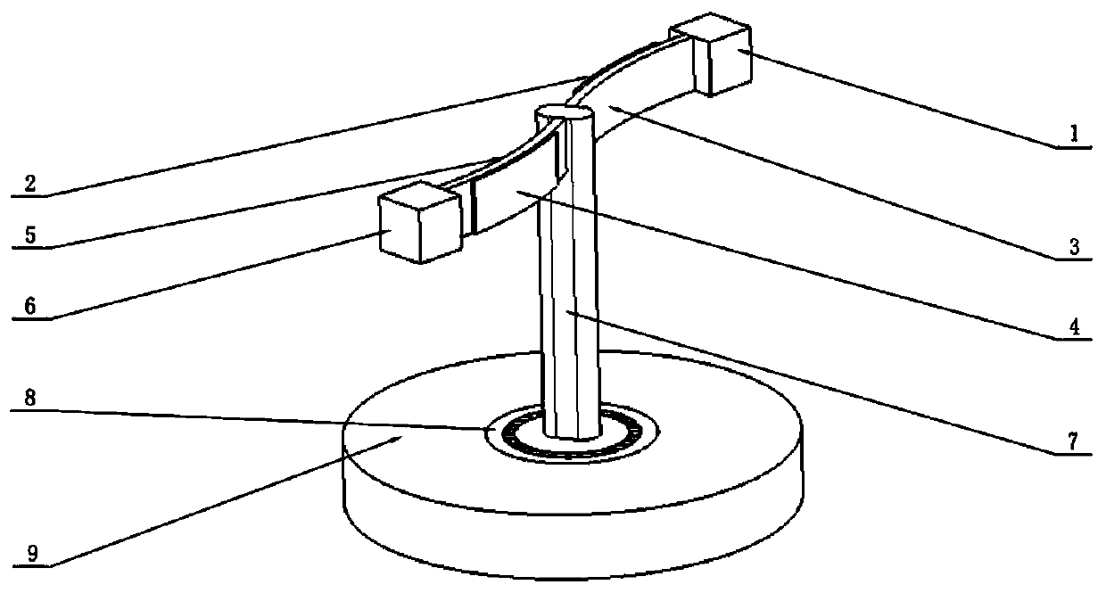
[0015] The invention relates to an inertial rotation drive device based on piezoelectric fibers, which is a new type of drive device that utilizes the inverse piezoelectric effect of piezoelectric fibers and the principle of inertial drive to drive a mechanism to realize rotation. Such as figure 1 As shown, the two ends of the metal plate 1 (3) are respectively connected to the mass block 1 (1) and the support (7), the two ends of the metal plate 2 (5) are respectively connected to the mass block 2 (6) and the support (7), and the mass block 1 (1) and mass block 2 (6) produce inertia force in the process of motion. The power source is two pieces of flexible piezoelectric fibers, a metal plate pre-bent to a certain radian is bonded to the piezoelectric fibers and a mass block is connected at one end to form an actuator as a whole. The piezoelectric fiber and the metal plate are bonded in parallel with conductive glue. Metal plate 1 (3), metal plate 2 (5) are processed into a ...


PUM


Abstract

The invention discloses a piezoelectric fibre-based inertial rotating driving device. The piezoelectric fibre-based inertial rotating driving device comprises an actuator, a supporting post, a rolling bearing and a bottom plate. Piezoelectric fibres are adhered to metal plates which are pre-bent to a certain radian; one ends of the metal plates are connected with mass blocks to form the actuator integrally; the other ends of the metal plates are fixed to the supporting post; the supporting post is connected with the bottom plate through the rolling bearing. The piezoelectric fibres stretch and deform under the action of an alternating voltage, so that bending moment is generated on the surface of the metal plates; the other ends of the metal plates are connected with the mass blocks, so that inertia force is generated by the mass blocks in a moving process. Under the excitation of an electric signal, the piezoelectric fibres stretch and deform simultaneously, and the metal plates drive the mass blocks to rotate clockwise quickly to generate inertia impact force in an anti-clockwise direction; the overall device rotates anti-clockwise, then the input electric signal is changed, the metal plates are recovered, and the device is recovered to an original state to complete a period of motion. The device can also rotate clockwise in the mode of changing the input electric signal.

Description

technical field [0001] The invention belongs to the field of precision mechanical drive. It is used in micro-robot drive, micro-miniature machinery, etc. Background technique [0002] In recent years, with the rapid development of micro-nano technology, there is a demand for micro-mechanical drive technology in the technical fields of biomedical engineering, precision machinery, robots, computers, automatic control, precision measurement, micro-manufacturing of precision devices, and ultra-precision machining. increasing day by day. Traditional precision drive mainly adopts mechanical type, such as precision screw pair, rolling slide guide rail, precision spiral wedge mechanism, etc., but due to the existence of gaps, friction, crawling and other problems, its precision is difficult to meet the requirements. Under this condition, the developed Many new driving methods, such as electrostatic attraction, electromagnetic, magnetostrictive, shape memory alloy and piezoelectric...

Claims


Application Information

Patent Timeline
Patent Type & Authority Patents(China)
IPC IPC(8): H02N2/00
Inventor 董景石刘畅曹义朱晓刚徐智吴越杨志刚赵宏伟
Owner JILIN UNIV
Why Eureka
Try Eureka