

Electromagnetic wave cell based on array antennas
An array antenna and electromagnetic wave chamber technology, applied in radio transmission systems, electrical components, transmission monitoring and other directions, can solve the problems of low test accuracy, uneven distribution of simulated electromagnetic waves, and high requirements for the placement of the DUT, and achieve test accuracy. Raised, regular structure, small size effect
- Summary
- Abstract
- Description
- Claims
- Application Information
AI Technical Summary
Problems solved by technology
Method used
Image

Examples
Embodiment Construction
[0021] In order to make the object, technical solution and advantages of the present invention clearer, the present invention will be further described in detail below in conjunction with the accompanying drawings and embodiments. It should be understood that the specific embodiments described here are only used to explain the present invention, not to limit the present invention.
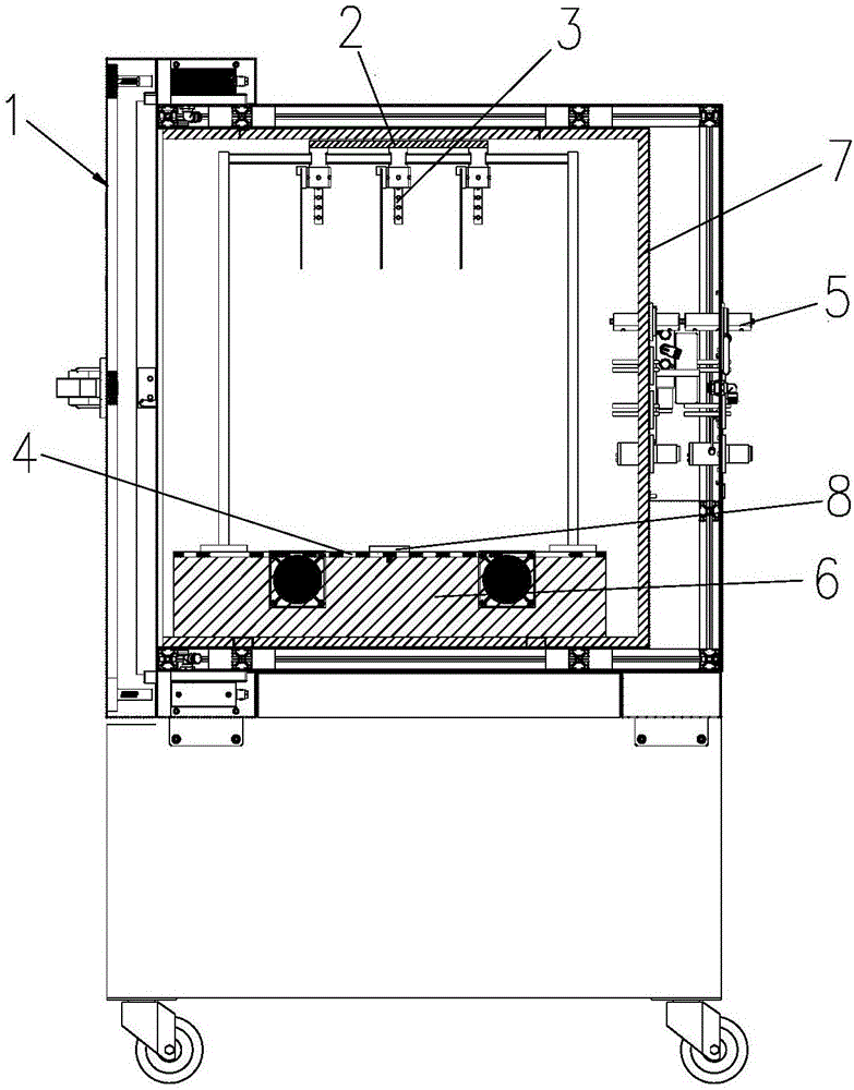
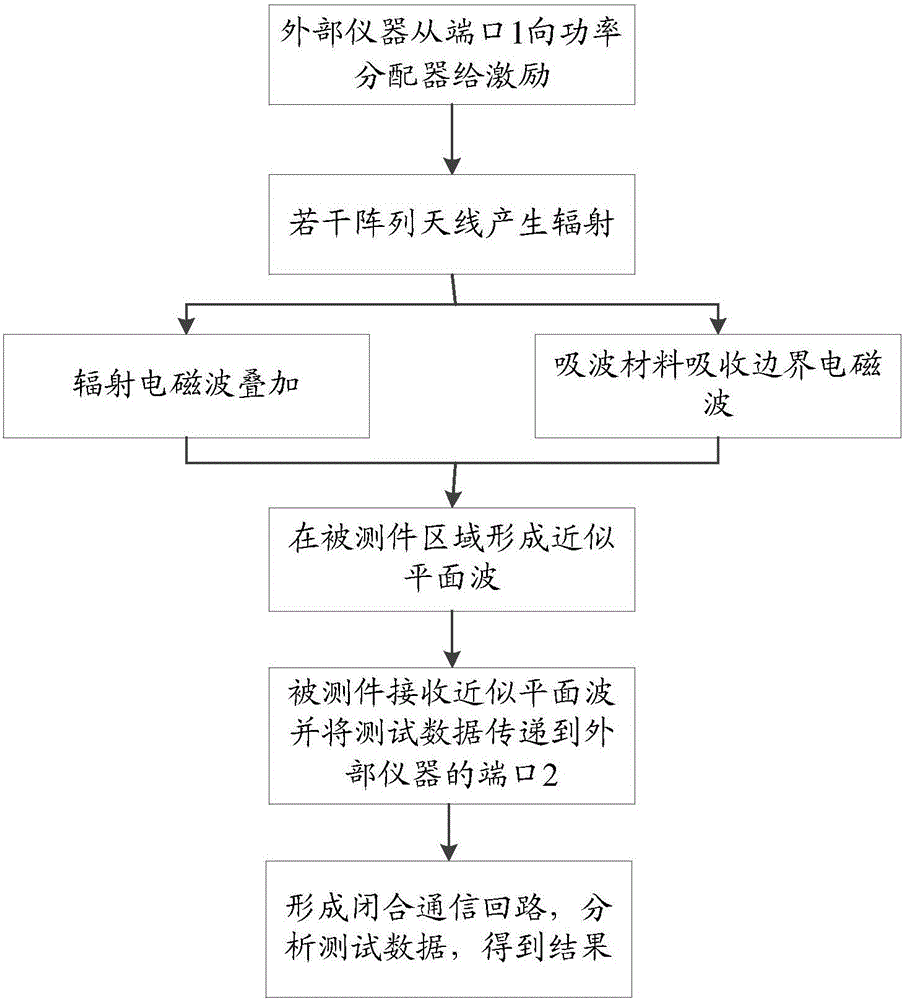
[0022] The main idea of the present invention is to design an electromagnetic wave chamber based on array antennas, in which several array antennas, power dividers and high-speed data filtering interfaces are designed, and the power divider is placed in the electromagnetic wave chamber and connected to the several array antennas; when external instruments provide excitation signals to the electromagnetic wave chamber, the power divider equally divides the excitation signals to the several array antennas, and the several array antennas generate The radiation signal is superimposed to form a quiet ...
PUM
 Abstract
Description
Claims
Application Information