A routing reflector-based path optimization method and system

A reflector and router technology, applied in the field of data communication, can solve the problems of not considering the resource utilization of the entire network, link congestion, and inability to achieve cross-domain multi-homing network load balancing, etc., to achieve multi-path load balancing and reduce processing. burden effect

Active Publication Date: 2020-03-31
CHINA TELECOM CORP LTD
View PDF5 Cites 0 Cited by
  • Summary
  • Abstract
  • Description
  • Claims
  • Application Information

AI Technical Summary

Problems solved by technology

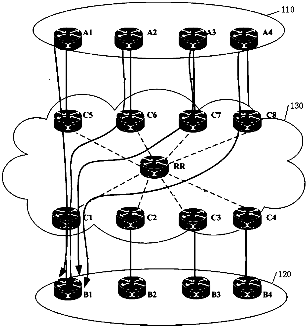
[0003] 1. The principle of uniqueness in route selection causes RR to only reflect the only preferred route to the routers in the entire network, causing some links to be congested, while other links are often empty or lightly loaded, making it impossible to achieve multi-path load balancing of traffic
[0004] 2. Since the RR selects a route with the closest IGP distance based on the IGP metric (Metric) value from itself to the advertising router (next hop), this preferred route is related to the location of the RR, and cannot represent other routers in the entire network to this route. The selected BGP next hop is the closest, and the lack of the perspective of the entire network topology leads to the generation of suboptimal routes
[0005] 3. Without considering the resource utilization of the entire network, it is impossible to realize the traffic engineering of the entire network
[0006] 4. RR follows the standard BGP route selection principle and cannot realize the traffic distribution according to the planned path
One limitation of ordinary RR following the standard BGP route selection principle is the uniqueness of route selection, that is, when it receives multiple routes from the same destination network, it only selects the route it thinks is the best, so cross-domain multi-homing cannot be realized Network load balancing

Method used


Image

  • A routing reflector-based path optimization method and system
  • A routing reflector-based path optimization method and system
  • A routing reflector-based path optimization method and system

Examples


Embodiment Construction

[0034] Various exemplary embodiments of the present invention will now be described in detail with reference to the accompanying drawings. It should be noted that the relative arrangements of components and steps, numerical expressions and numerical values ​​set forth in these embodiments do not limit the scope of the present invention unless specifically stated otherwise.

[0035] At the same time, it should be understood that, for the convenience of description, the sizes of the various parts shown in the drawings are not drawn according to the actual proportional relationship.

[0036] The following description of at least one exemplary embodiment is merely illustrative in nature and in no way taken as limiting the invention, its application or uses.

[0037] Techniques, methods, and devices known to those of ordinary skill in the relevant art may not be discussed in detail, but where appropriate, techniques, methods, and devices should be considered part of the authorized ...


PUM


Abstract

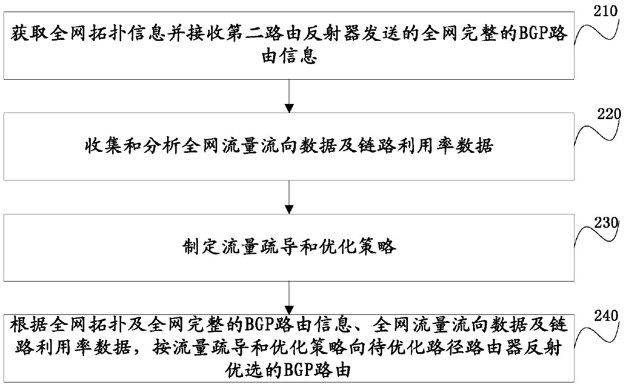
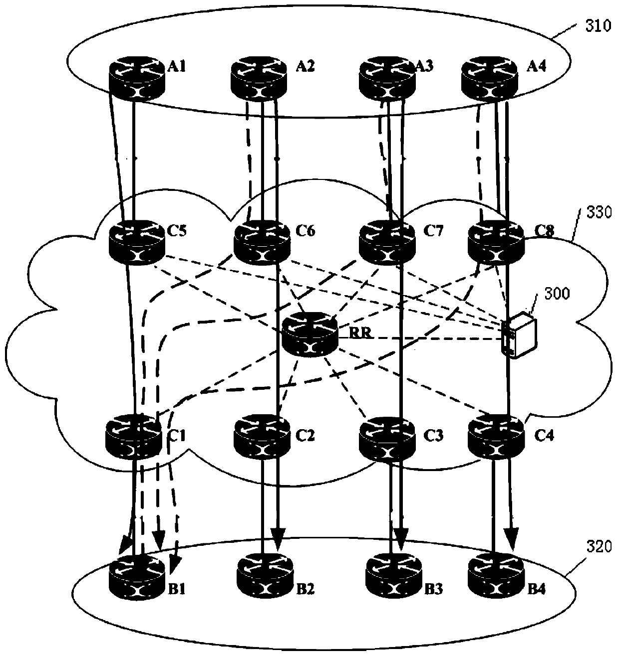
The invention discloses a path optimization method and system based on a route reflector, and relates to the field of data communication. The method includes: the first route reflector obtains the topology information of the whole network and receives the complete BGP routing information of the whole network sent by the second route reflector; the first route reflector collects and analyzes the traffic flow data and link utilization rate of the whole network data, and formulate traffic grooming and optimization strategies; the first route reflector according to the traffic grooming and optimization strategy to the optimized Path routers reflect preferred BGP routes. It can realize multi-path load balancing of traffic, and avoid the problem of suboptimal routing caused by the lack of perspective of the whole network topology. In addition, because the first route reflector only needs to establish IBGP connections with routers involved in path optimization, this can reduce the processing load of the first route reflector.

Description

technical field [0001] The present invention relates to the field of data communication, in particular to a routing reflector-based path optimization method and system. Background technique [0002] In the prior art, when a route reflector (Route Reflector, RR) receives multiple routes of the same destination network, due to following the standard BGP route selection principle, there are the following limitations: [0003] 1. The principle of uniqueness in route selection causes RR to only reflect the only preferred route to routers in the entire network, causing some links to be congested, while other links are often empty or lightly loaded, making it impossible to achieve multi-path load balancing of traffic. [0004] 2. Since the RR selects a route with the closest IGP distance based on the IGP metric (Metric) value from itself to the advertising router (next hop), this preferred route is related to the location of the RR, and cannot represent other routers in the entire ...

Claims


Application Information

Patent Timeline
Patent Type & Authority Patents(China)
IPC IPC(8): H04L12/707H04L12/753H04L45/24
CPCH04L45/24H04L45/48
Inventor 何晓明
Owner CHINA TELECOM CORP LTD
Why Eureka
Try Eureka