Supercharge Your Innovation With Domain-Expert AI Agents!

Vertical air duct cooling chassis

A vertical air duct and chassis technology, which is applied in the field of vertical air duct heat dissipation chassis, can solve the problems of low heat dissipation efficiency of the chassis, and achieve the effects of easy cleaning, increased heat dissipation speed, and improved heat dissipation efficiency

Inactive Publication Date: 2020-06-05
CHONGQING CHENGSHUO TECH
View PDF8 Cites 1 Cited by
  • Summary
  • Abstract
  • Description
  • Claims
  • Application Information

AI Technical Summary

Problems solved by technology

[0005] Aiming at the technical problem of low heat dissipation efficiency of the existing chassis, the present invention provides a vertical air duct type heat dissipation chassis capable of efficiently dissipating heat

Method used


Image

  • Vertical air duct cooling chassis
  • Vertical air duct cooling chassis
  • Vertical air duct cooling chassis

Examples


Embodiment 1

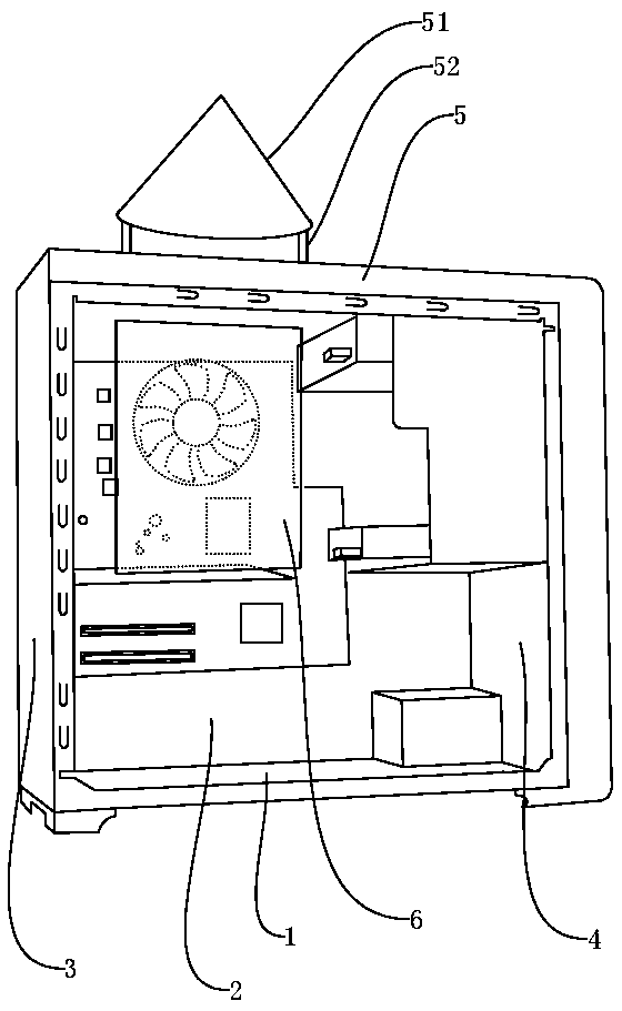
[0031] Basic as attached figure 1 , figure 2 Shown: the vertical air duct type heat dissipation cabinet of this embodiment, including:

[0032] Bottom plate, the bottom plate is uniformly provided with ventilation holes, the bottom plate is bonded with a sponge dust-proof pad, and there are fixed connectors around the sponge dust-proof pad. The connectors are made of rectangular plastic products with the same shape as the bottom plate. Threaded connection with the bottom plate;

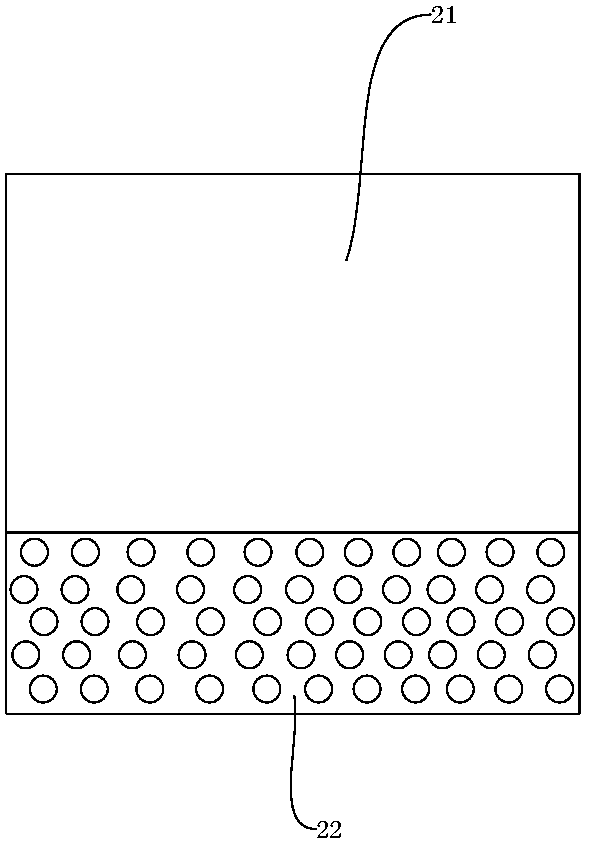
[0033] Two side plates, the side plates are all hollow structures, both include an outer plate 21 and an inner plate 22, the inner plates 22 are respectively fixed on both sides of the bottom plate by welding, and are perpendicular to the plane where the bottom plate is located, and the bottom of the inner plate 22 is provided with The air inlet, the air inlet is provided with an exhaust fan, and the air inlet is provided with a dust-proof thin net made of teda. Set the separator 23 (such as ima...

Embodiment 2

[0040] Compared with Embodiment 1, the difference is that a water storage tank 7 is provided under the inner panel 22, and the water storage tank 7 is located below the air inlet (such as Figure 4 As shown), the deflector 6 is provided with fins in the vertical direction, and the deflector 6 is provided with grooves for fixing the fins, and the fins are embedded in the grooves. The fins can better guide the graphics card and the CPU out of the air outlet, and the fins are detachably connected to the deflector 6, which is convenient for cleaning.

Embodiment 3

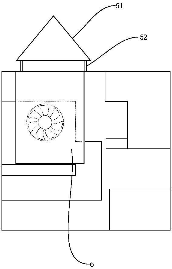
[0042] Compared with Embodiment 2, the difference lies in that an air guide tube is provided between the connecting rod 52 and the cover plate 5 , and the air guide tube is screwed to the cover plate 5 . The air duct can further enhance the effect of the chimney effect, speed up the flow rate of air in the chassis, and further improve the heat dissipation effect.


PUM


Abstract

The invention relates to the field of computer accessories, in particular to a vertical air duct heat dissipating case. The vertical air duct heat dissipating case comprises a bottom plate, two side plates and a back plate, wherein vent holes are uniformly formed in the bottom plate, a sponge dustproof pad is arranged on the bottom plate, and connecting pieces are fixedly arranged on the periphery of the sponge dustproof pad, are rectangular as the bottom plate and connected with the bottom plate through threads; each side plate is of a hollow structure and comprises an outer plate and an inner plate, the inner plates are fixed to the two sides of the bottom plate respectively and are perpendicular to the plane where the bottom plate is located, an air inlet is formed in the lower portion of each inner plate and provided with a thin dustproof net made of tactel, the outer plates are located above the air inlets, and partition plates are arranged between the outer plates and the inner plates in the vertical direction; air inlet holes are formed in the lower portion of the back plate. The vertical air duct heat dissipating case capable of dissipating heat efficiently is provided to solve the technical problem that an existing case is low in heat dissipation efficiency.

Description

technical field [0001] The invention relates to the field of computer accessories, in particular to a vertical air duct type cooling case. Background technique [0002] With the continuous development of semiconductor technology, computers continue to develop towards the trend of small size, high performance and powerful functions. The existing heat dissipation system of the main chassis cannot guarantee good heat dissipation due to performance limitations. Therefore, in order to ensure the performance of each component in the heat dissipation system of the main chassis, it is necessary to ensure that the heat dissipation system of the main chassis has good heat dissipation performance. [0003] Existing CPU is directly installed on the mainboard, and mainboard is vertically installed in the casing, and graphics card and mainboard are vertically installed on the mainboard, and from vertical direction, CPU and graphics card are in two parts. [0004] There is an urgent need ...

Claims


Application Information

Patent Timeline
Patent Type & Authority Patents(China)
IPC IPC(8): G06F1/18G06F1/20
CPCG06F1/181G06F1/183G06F1/20
Inventor 陈佳英
Owner CHONGQING CHENGSHUO TECH
Features
  • R&D
  • Intellectual Property
  • Life Sciences
  • Materials
  • Tech Scout
  • Unparalleled Data Quality
  • Higher Quality Content
  • 60% Fewer Hallucinations
Learn More