

Curved screen installation structure
A technology of installation structure and curved screen, applied in the casing with display/control unit, electrical components, chassis/cabinet/drawer parts, etc. Shock-resistant, fully sealed, and the effect of avoiding display damage
- Summary
- Abstract
- Description
- Claims
- Application Information
AI Technical Summary
Problems solved by technology
Method used
Image

Examples
Embodiment 1
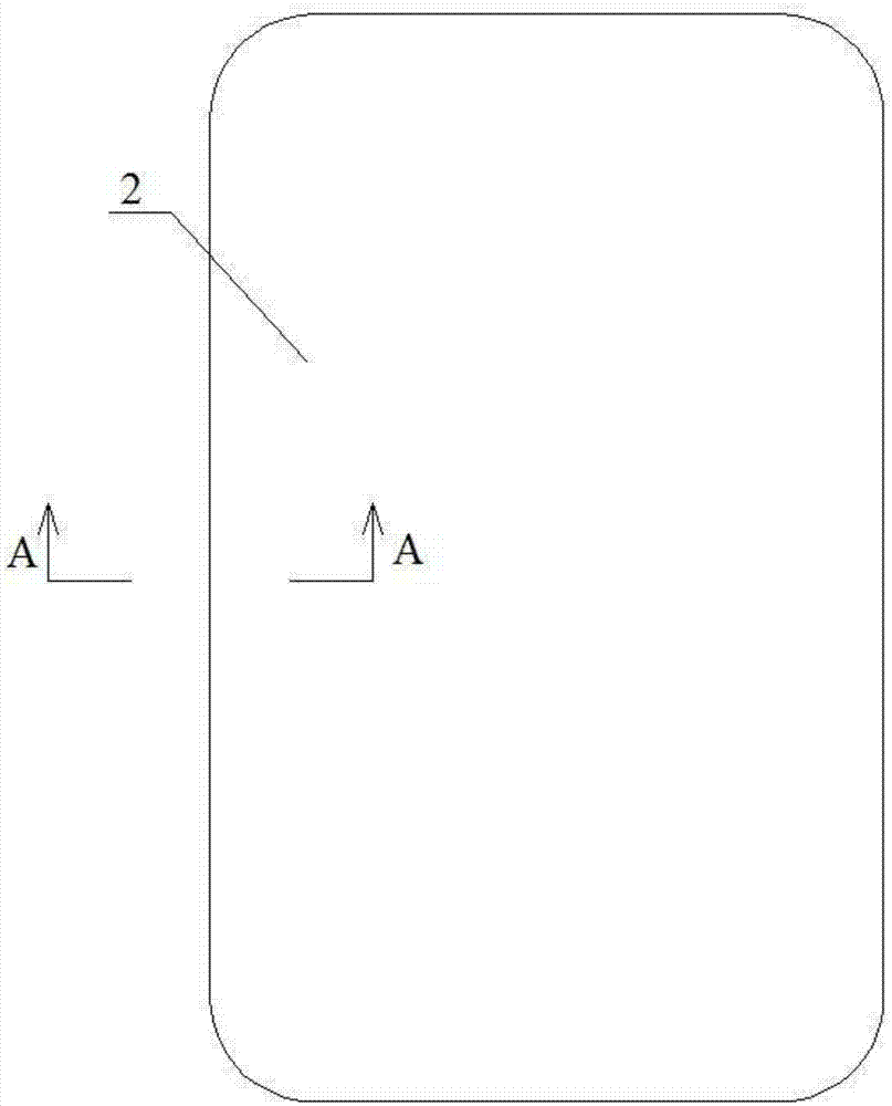
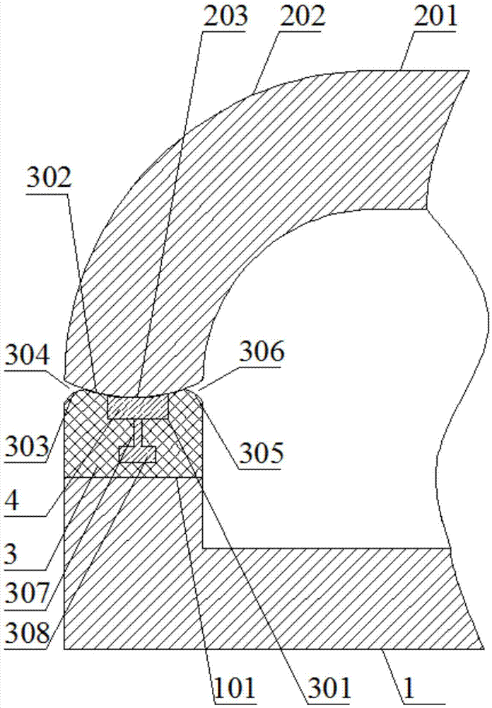
[0030] Such as figure 1 and figure 2 As shown, the installation structure of the curved screen includes an outer frame 1, a display screen 2 and a rubber ring 3; Fixed on the fixed surface 101; the top of the rubber ring 3 is provided with a hot-melt adhesive receiving groove 301, and the hot-melt adhesive receiving groove 301 extends for a week along the top of the rubber ring 3; Outwardly extending arc portion 202, the bottom of the arc portion 202 is attached to the top of the rubber ring 3, the bottom of the arc portion 202 completely covers the hot melt adhesive holding groove 301 and closes the hot melt adhesive holding groove 301; The groove 301 is filled with hot melt glue 4; the bottom of the hot melt glue holding groove 301 is uniformly provided with a plurality of vertical blind holes 307 for the hot melt glue to pass through under pressure, and the diameter of the vertical blind holes 307 is 1 mm; the rubber ring 3 An accommodating chamber 308 communicating with...
Embodiment 2
[0035] Such as figure 2 As stated above, on the basis of Embodiment 1, the bottom cross-section of the arc-shaped portion 202 is an arc surface A203; the top cross-section of the rubber ring 3 is an arc surface matched with the arc surface A203 B302.
[0036] The arc surface A203 and the arc surface B302 are provided to increase the contact area between the display screen 2 and the rubber ring 3, so that the display screen 2 is fixed more firmly.
Embodiment 3
[0038] Such as figure 2 As mentioned above, this embodiment is based on Embodiment 1, the top outer edge of the rubber ring 3 is rounded to form a rounded surface A303; a gap is formed between the rounded surface A303 and the bottom of the arc portion 202 A304.
[0039] When the rubber ring 3 is impacted and deformed, the gap A304 provides a space for the deformation of the outer edge of the rubber ring 3, preventing the rubber ring 3 from directly squeezing the display screen 2 when the rubber ring 3 is impacted and deformed, and preventing the display screen 2 from being damaged under pressure.
PUM
 Abstract
Description
Claims
Application Information