Cutter row used for reverse turning of end face on vertical lathe

A technology of turning end faces and cutter rows, applied in the direction of tool holders, etc., can solve problems such as processing quality and safety hazards, poor flatness of the processing surface, and product quality impact, and achieve long processing time, low probability of fracture, and guaranteed processing. quality effect

Inactive Publication Date: 2017-06-20
ANHUI HELI CO LTD
View PDF10 Cites 2 Cited by
  • Summary
  • Abstract
  • Description
  • Claims
  • Application Information

AI Technical Summary

Problems solved by technology

However, due to the large processing surface of some parts, the overhang of the tool should be increased correspondingly when reverse turning, which will generate a greater impact on the knife row, and the knife row is easy to vibrate, and the wall thickness of the stressed side is less likely to cause cracking Phenomenon, the flatness of the processing surface is not good, which affects the product quality, and there are processing quality and safety hazards

Method used


Image

  • Cutter row used for reverse turning of end face on vertical lathe
  • Cutter row used for reverse turning of end face on vertical lathe
  • Cutter row used for reverse turning of end face on vertical lathe

Examples


Embodiment Construction

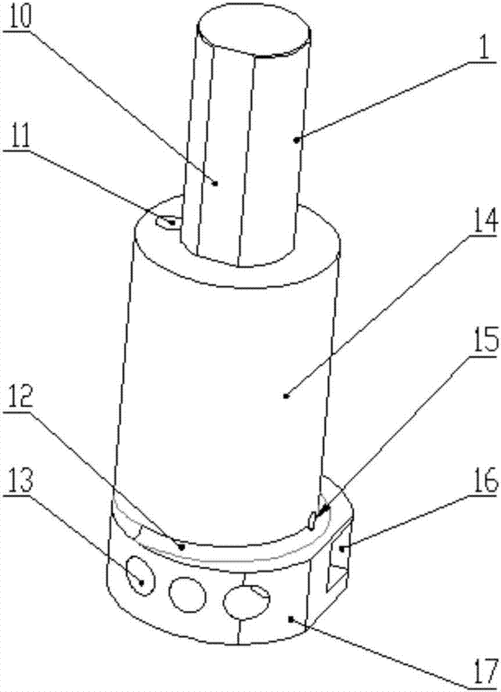
[0021] like figure 1 The cutter row used for the upper and reverse turning end of the vertical lathe includes a cylindrical cutter rod 1 with a mounting and positioning plane on the side; it is fixed at the lower end of the cutter rod 1 and the cutter rod forms a cylinder with a stepped shaft shape concentric with the central axis Shape knife row middle part 14; Be fixed at the bottom 17 of cylindrical knife row bottom 17 of non-concentric axis step axis shape that is fixed on the bottom of knife row middle part 14 and cylindrical knife row middle part 14; Be located at the cutter on the bottom 17 sides of cylindrical knife row; The connection between the bottom 17 of the cylindrical knife row and the middle part 14 of the cylindrical knife row is provided with an excessively rounded corner 12, through the setting of the excessively rounded corner 12, the damage to the knife row caused by the stress concentration of the product when the knife row is used is reduced, and it can ...


PUM


Abstract

The invention belongs to the technical field of cutter rows, and particularly relates to a cutter row used for reverse turning of the end face on a vertical lathe. The cutter row is characterized by comprising a cylindrical cutter row rod with the side face provided with an installing positioning plane, a cylindrical cutter row middle part fixedly arranged at the lower end of the cutter row rod and forming a concentric step shape with the cutter row rod, a cylindrical cutter row bottom part fixedly arranged at the lower end of the cutter row middle part and forming a non-concentric step shaft shape with the cylindrical cutter row middle part, and a cutter arranged on the side face of the cylindrical cutter row bottom part. A transition circular bead is arranged at the connecting position of the cylindrical cutter row bottom part and the cylindrical cutter row middle part. The cutter row rod, the cutter row middle part and the cutter row bottom part are integrally formed. The cutter row is high in stress strength, good in anti-knock performance and low in manufacturing cost, safety is achieved during using, the quality of machined products can be guaranteed, and the machining efficiency is high.

Description

technical field [0001] The invention belongs to the technical field of vertical lathe parts processing, and in particular relates to a cutter row used for reverse turning end faces of vertical lathes. Background technique [0002] During the processing of parts on the vertical lathe, in order to ensure the processing quality, that is, to ensure the coaxiality under normal circumstances, one-time clamping is often adopted, which will cause some processing surfaces to be difficult to process from the tool feed direction, so the processing of these surfaces Processing requires reverse turning, that is, moving the tool from far to near for processing. However, due to the large processing surface of some parts, the overhang of the tool should be increased correspondingly when reverse turning, which will generate a greater impact on the knife row, and the knife row is easy to vibrate, and the wall thickness on the stressed side is less likely to cause cracking Phenomenon, the fla...

Claims


Application Information

Patent Timeline
Patent Type & Authority Applications(China)
IPC IPC(8): B23B29/04
CPCB23B29/04
Inventor 张三宝袁兵昌张琴张洪权陈浩
Owner ANHUI HELI CO LTD
Why Eureka
Try Eureka