
Numerical control positioning system with automatic height measuring function
A positioning system and automatic height measurement technology, applied in the direction of measuring/indicating equipment, metal processing equipment, metal processing machinery parts, etc., can solve the problems of low measurement efficiency and poor measurement accuracy, and achieve strong versatility and high accuracy , a wide range of effects
- Summary
- Abstract
- Description
- Claims
- Application Information
AI Technical Summary
Problems solved by technology
Method used
Image

Examples
Embodiment Construction
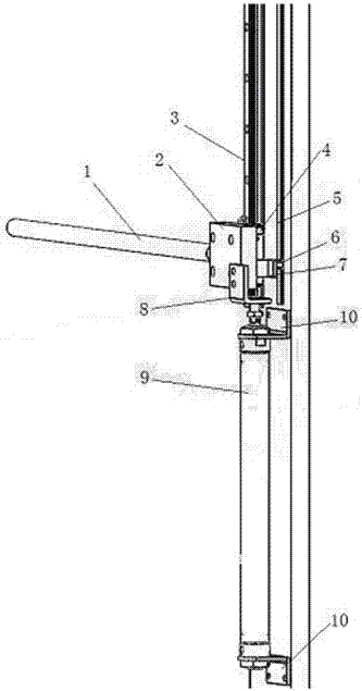
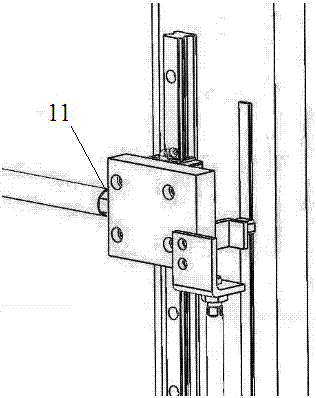
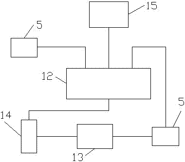
[0017] Such as figure 1 , figure 2 , image 3 and Figure 4 As shown, a numerically controlled positioning system with automatic height measurement is composed of a height measurement device, a PLC controller 12, a motor 13, a frequency converter 14, and a touch screen 15. The height measurement device includes a measuring rod 1, a slide mounting block 2, a height The precision flat guide rail 3, the high-precision slider 4, the magnetic ruler 5, the reading head 6 and the cylinder 9 are composed. The cylinder 9 is fixed by the cylinder mounting seat 10, and the piston rod of the cylinder 9 is connected with the slide mounting block 2 through the cylinder connector 8. One side of the sliding seat mounting block 2 is connected with the measuring rod 1, and the other side of the sliding seat mounting block 2 is connected with the reading head 6 through the reading head connecting piece 7. Move on the guide rail 3, set the magnetic ruler 5 on one side of the high-precision fl...
PUM
 Abstract
Description
Claims
Application Information