Grinding tool for numerical control die shearing cutter edge

A knife edge and die technology, applied in the field of CNC die shearing knife edge grinding tooling, can solve the problems of troublesome angle adjustment, affecting normal work, cumbersome operation process, etc., to reduce production difficulty and manufacturing cost, reduce clamping difficulty, and overall structure simple effect

Active Publication Date: 2017-06-20
CHANGSHU BOZE NC ELECTRICAL & MECHANICAL PARTS FACTORY
View PDF6 Cites 0 Cited by
  • Summary
  • Abstract
  • Description
  • Claims
  • Application Information

AI Technical Summary

Problems solved by technology

[0002] The shearing edge grinding tool is a tool that clamps the tool and can adjust a certain angle. The main structure of the shearing edge grinding tool on the market is: the three-legged jaw clamps the tool by tightening the locking screw. When When changing the tool, the tripod claws must be loosened or tightened with a special tool, which is labor-intensive and time-consuming, and the efficiency of disassembly and installation is low. In addition, the tool is often loosened due to the screw not being tightened, which affects normal work.
Moreover, the angle adjustment of the above-mentioned shearing edge grinding tool is also relatively troublesome. It is realized by a combination of a rotating mechanism and an angle mark. Not only is the operation process very cumbersome, but also the angle adjustment takes a long time. A certain position deviation will affect the service life
In addition, the price of this kind of cutting edge grinding tooling is generally high, which cannot meet the needs of consumers

Method used


Image

  • Grinding tool for numerical control die shearing cutter edge

Examples


Embodiment Construction

[0013] The applicant will describe in detail in the form of the following examples, but the description of the examples is not a limitation to the technical solution of the present invention, and any equivalent transformation made according to the concept of the present invention is only a formal rather than a substantive equivalent transformation All should be regarded as the scope of the technical solution of the present invention.

[0014] In the following descriptions, all concepts related to directionality or orientation of up, down, left, right, front and back are based on figure 1 The position shown is a reference, so it cannot be understood as a special limitation on the technical solution provided by the present invention.

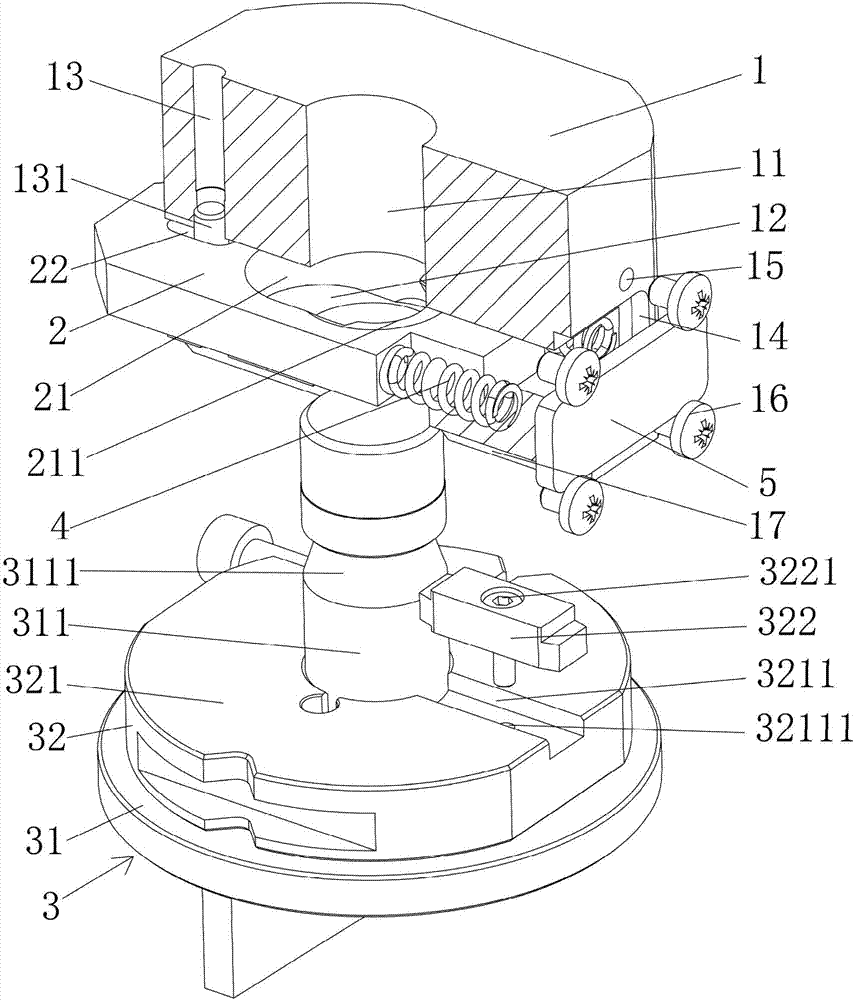
[0015] see figure 1 , the present invention relates to a CNC punching die shearing edge grinding tool, comprising a punch seat 1, claws 2 and a punch 3 for cooperating with the punch seat 1, the punch seat 1 is set in the middle of the height dir...


PUM


Abstract

A grinding tool for a numerical control die shearing cutter edge comprises a punch seat, a clamping jaw and a punch. An upper-down-through cutter handle hole and a left-right-through clamping jaw mounting hole are formed in the middle of the punch seat. The cutter handle hole is perpendicular to the clamping jaw mounting hole and communicates with the clamping jaw mounting hole. One end of the clamping jaw mounting hole is closed through a jacking plate. The clamping jaw is arranged in the clamping jaw mounting hole. The end, away from the jacking plate, of the clamping jaw extends out of the clamping jaw mounting hole, and the other end of the clamping jaw abuts against the jacking plate through springs; a clamping opening is formed in the middle of the clamping jaw, and a tapered clamping foot is arranged in the clamping opening; the punch is composed of a cutter and a calibration ring; the cutter is fixed to the axial middle portion of the calibration ring, a clamping groove is formed in a cutter handle of the cutter, the punch and the cutter handle hole of the punch seat are mounted in a matched manner through the cutter handle, and the tapered clamping foot and the clamping groove are mutually embedded in a matched manner so that fast fixed connection of the punch and the punch seat can be achieved; the clamping speed is increased, and the clamping difficulty is lowered; mounting is convenient and fast, and the precision is high; and fast reversing of the punch on the punch seat can be achieved; and the structure is simple, and the production difficulty and the manufacturing cost of the tool are lowered.

Description

technical field [0001] The invention belongs to the technical field of tool clamping devices, and in particular relates to a cutting edge grinding tool for a numerically controlled punching die. Background technique [0002] The shearing edge grinding tool is a tool that clamps the tool and can adjust a certain angle. The main structure of the shearing edge grinding tool on the market is: the three-legged jaw clamps the tool by tightening the locking screw. When When changing the tool, the tripod claw must be loosened or tightened with a special tool, which is labor-intensive and time-consuming, and the disassembly and installation efficiency is low, and the tool is often loosened due to the screw not being tightened, which affects normal work. Moreover, the angle adjustment of the above-mentioned shearing edge grinding tool is also relatively troublesome. It is realized by a combination of a rotating mechanism and an angle mark. Not only is the operation process very cumber...

Claims


Application Information

Patent Timeline
IPC IPC(8): B24B37/34B24B41/00
CPCB24B37/34B24B41/00
Inventor 钱江
Owner CHANGSHU BOZE NC ELECTRICAL & MECHANICAL PARTS FACTORY
Why Eureka
Try Eureka