Electric safety clamp technology capable of rapidly conducting releasing and clamping

A safety clamping and fast technology, applied in the direction of clamping, manufacturing tools, workpiece clamping devices, etc., can solve problems such as low efficiency, excessive clamping force, and clamping marks on the workpiece, and achieve the effect of flexible operation

Inactive Publication Date: 2017-06-20
姜序敏
View PDF9 Cites 2 Cited by
  • Summary
  • Abstract
  • Description
  • Claims
  • Application Information

AI Technical Summary

Problems solved by technology

[0004] At present, machine tool fixtures or vises and vises of manual tools are generally clamped manually to ensure moderate clamping force, which is inefficient; when hydraulic or electric clamps are used, the clamping force is difficult to control, and it is difficult to apply to thin-walled Clamping of parts or pressure-sensitive parts: On the one hand, automatic clamps are often used for manual correction to ensure safe production. Manual correction requires additional force to overcome the resistance of the driving tool, and it is difficult to judge the effective force and clamping effect; on the other hand The automatic fixture has the disadvantages of too large or too small clamping force, and then there are disadvantages such as excessive deformation of the workpiece, leaving clamp marks on the workpiece, or potential safety hazards due to ineffective clamping.

Method used


Image

  • Electric safety clamp technology capable of rapidly conducting releasing and clamping
  • Electric safety clamp technology capable of rapidly conducting releasing and clamping
  • Electric safety clamp technology capable of rapidly conducting releasing and clamping

Examples


Embodiment Construction

[0026] Below in conjunction with schematic diagram, specific embodiment and assembly drawing, make further explanation:

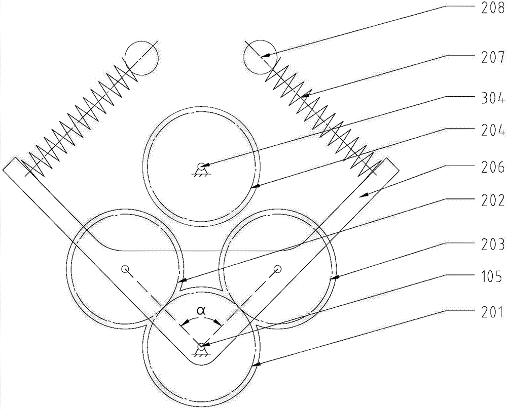
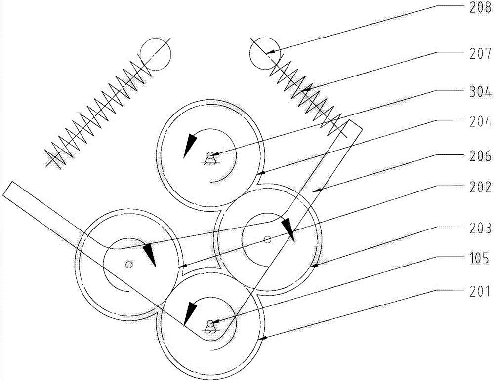
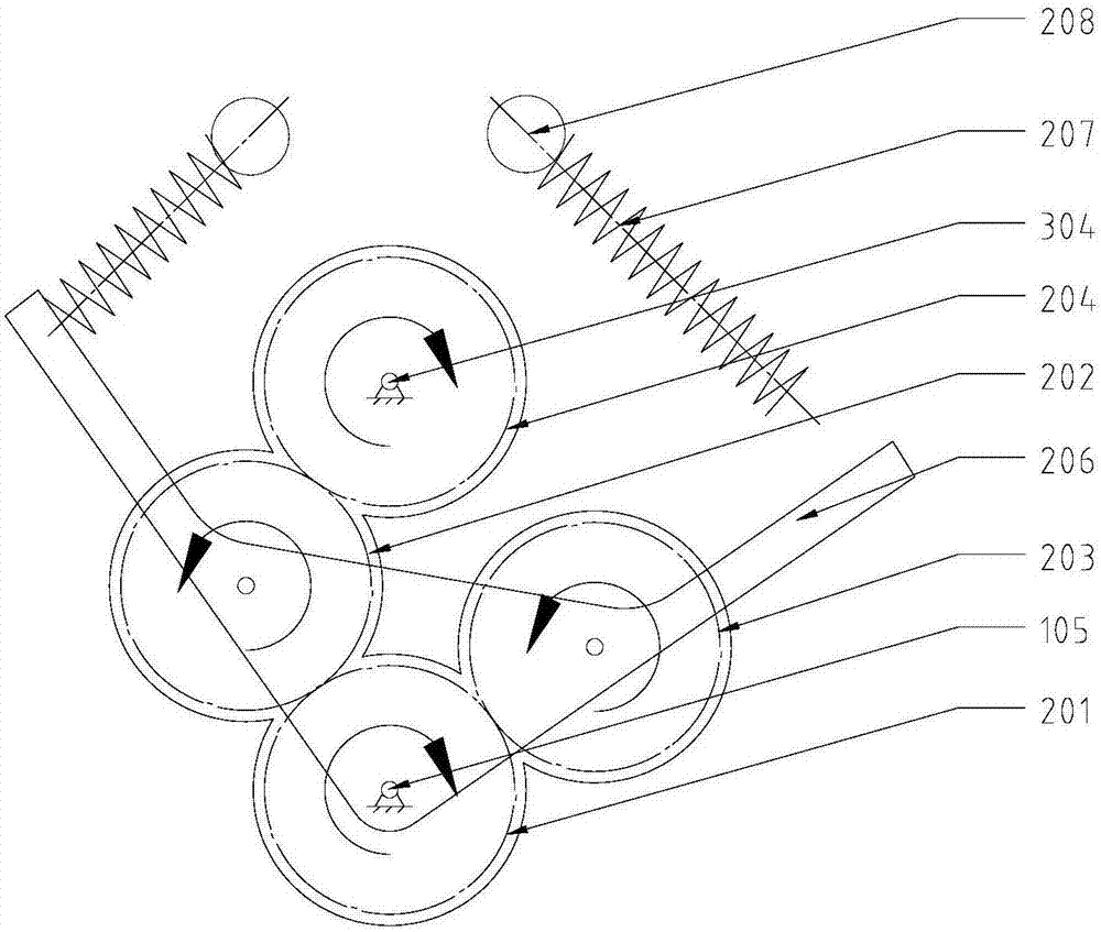
[0027] see Figure 4 , 5 , 6, 7, there is respectively a contact switch 401,402 at the travel limit position of the movable pliers 305 on the fixed pliers 310, and a pressure sensor switch 403 is arranged at the jaws of the fixed pliers 310; the fixed pliers 310 and the screw slider 307 is slidingly connected, and connected by screw 304 for transmission. The movable caliper body 305 is axially installed on the screw slider 307 and fixed with the fixing screw 306; one end of the screw 304 is a square shaft section 312, which is positioned by a backing ring 311 and matched with a corresponding The detachable handle can realize manual clamping, and the other side of the screw rod 304 is fixed with the driving gear 204, and the positioning of the axle sleeve 303, the fixing of the nut 301 and the cotter pin 302 are arranged; Drive gear 201, intermediate gear ...


PUM


Abstract

The invention relates to an electric safety clamp technology capable of rapidly conducting releasing and clamping, and belongs to an electronic control clamp technology. By controlling a motor to rotate forwards and backwards through switches, different engagement manners of varying contact gear sets are controlled, a threaded rod is then driven, jaws are rapidly driven to be opened and closed, and manual clamping is conducted in an auxiliary manner; by means of an arranged safety circuit, it is ensured that only contact force is exerted on workpieces and no large clamping force is exerted on the workpieces, and the practical valid clamping force is manually exerted; and the circuit cannot be closed until a movable caliper body is separated from all the switches through manual disassembling so that the motor can be driven and safety of the subsequent machining can be ensured. Under the condition that safety clamping is achieved, rapid workpiece clamping / disassembling is achieved, it is effectively avoided that the clamping quality is influenced by too much mechanical intervention, and the electric safety clamp technology is suitable for places where the workpieces are machined and clamped in a semiautomatic or manual manner and is particularly suitable for rapidly clamping thin-walled pieces or pressure-sensitive pieces.

Description

[0001] Technical field [0002] The invention relates to an electric quick-tightening safety clamp technology, in particular to a safety clamp technology with fast driving jaws, small initial pressure on clamped objects, and manual adjustment of clamping force. [0003] technical background [0004] At present, machine tool fixtures or vises and vises of manual tools are generally clamped manually to ensure moderate clamping force, which is inefficient; when hydraulic or electric clamps are used, the clamping force is difficult to control, and it is difficult to apply to thin-walled Clamping of parts or pressure-sensitive parts: On the one hand, automatic clamps are often used for manual correction to ensure safe production. Manual correction requires additional force to overcome the resistance of the driving tool, and it is difficult to judge the effective force and clamping effect; on the other hand Automatic fixtures have the disadvantages of too large or too small clamping ...

Claims


Application Information

Patent Timeline
Patent Type & Authority Applications(China)
IPC IPC(8): B25B11/00B23Q3/00B25B1/10B25B1/18
CPCB23Q3/00B25B1/10B25B1/18B25B11/00
Inventor 姜序敏刘东何苗张丽刘帅宋洪尘
Owner 姜序敏
Why Eureka
Try Eureka