
Paper cutting machine

A paper cutter and machine body technology, applied in metal processing and other fields, can solve problems such as unsafety, reduced work efficiency, and work-related accidents

Inactive Publication Date: 2017-06-20
高晶
View PDF11 Cites 6 Cited by
  • Summary
  • Abstract
  • Description
  • Claims
  • Application Information

AI Technical Summary

Problems solved by technology

The paper cutter with this structure needs to be shut down first to deal with the waste edges, resulting in a reduction in work efficiency. At the same time, there are unsafe factors to deal with the waste edges by manual operation, which often causes work-related accidents.
[0003] The invention patent with the Chinese patent authorization announcement number of CN102259348B discloses a paper cutter, including a machine body, a front operating platform and a rear operating platform, the rear operating platform is fixed on the machine body, and the front operating platform is movably installed on the machine body through a mobile device On the machine body, a baffle is hinged, and a first cylinder is installed on the body, and the push rod of the first cylinder is dynamically connected with the baffle; however, this kind of paper cutter has poor synchronization and it is difficult to collect waste edges stably. Problems Draining into the Waste Collection Bin

Method used


Image

  • Paper cutting machine

Examples


Embodiment Construction

[0022] The specific implementation manners of the present invention will be further described in detail below in conjunction with the accompanying drawings and embodiments. The following examples are used to illustrate the present invention, but are not intended to limit the scope of the present invention.

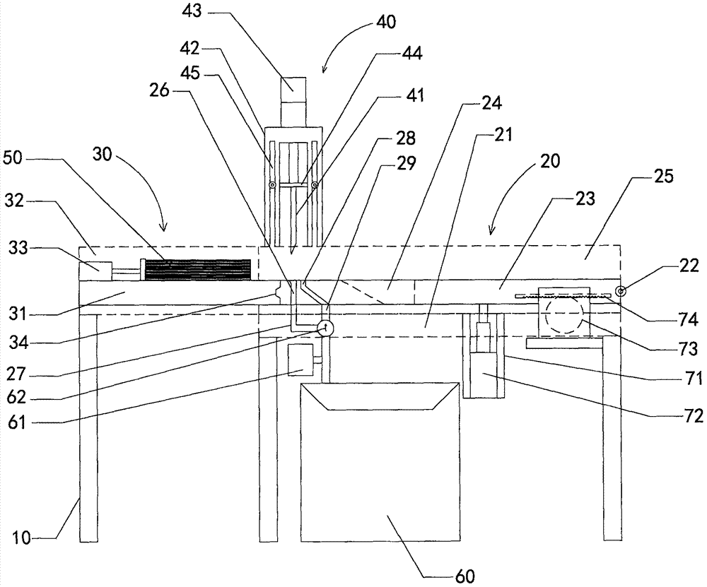
[0023] see figure 1 , a paper cutter according to a preferred embodiment of the present invention includes a body 10, a front console mechanism 20, a rear console mechanism 30, and a cutter mechanism 40, and the rear console mechanism 30 includes a rear operating mechanism fixed on the body. Table 31, the tailgate 32 arranged on the left and right sides of the rear console, and the pusher unit 33 arranged on the top surface of the rear console, the pusher unit is used to push the paper 50 to the bottom of the cutter mechanism 40; the front console The mechanism 20 includes a frame body 21, a front console 23 whose front end is connected to the frame body 21 through a rota...


PUM


Abstract

The invention relates to paper cutting machines, in particular to a paper cutting machine. The paper cutting machine comprises a machine body, a front operating floor mechanism, a rear operating floor mechanism and a cutter mechanism. The rear operating floor mechanism comprises a rear operating floor fixed to the machine body, rear baffles arranged at the left side and the right side of the rear operating floor and a material pushing unit arranged on the top face of the rear operating floor. The material pushing unit is used for pushing paper to the position below the cutter mechanism. The front operating floor mechanism comprises a frame body, a front operating floor with the front end being connected to the frame body through a rotating shaft, a displacement unit and a lifting unit which is arranged at the bottom of the frame body. The lifting unit is used for controlling the front operating floor to rotate relatively around the rotating shaft. The cutter mechanism is fixed to the top of the rear end of the frame body and comprises a cutter making reciprocating motion relative to the front operating floor. The front operating floor is provided with a material falling opening. A waste tank is arranged on the machine body and located below the material falling opening. According to the paper cutting machine, paper waste edges can be removed automatically, and operating stability is high.

Description

technical field [0001] The invention relates to a paper cutting machine, in particular to a paper cutting machine. Background technique [0002] At present, paper cutters are used to cut paper of various specifications. When cutting paper, one side of the whole stack of paper must be cut flat first, and then cut according to the specifications, and the waste edges generated during cutting must be Clean up first before cutting paper. Especially for some cut and printed paper, some marking lines must be cut off, resulting in a lot of waste edges. In the prior art, the basic mechanism of the paper cutter is the body, the front and rear consoles, and the cutter. The stacked paper is transferred and processed through the front operation table. The paper cutter of this structure all will be shut down earlier after cutting the waste edge, and after the waste edge that cuts is manually cleaned, start to cut paper again. The paper cutter of this structure, owing to needing to shu...

Claims


Application Information

Patent Timeline
IPC IPC(8): B26D1/06B26D7/06B26D7/26B26D5/12B26D7/18
CPCB26D1/06B26D5/12B26D7/0608B26D7/18B26D7/1818B26D7/2614
Inventor 高晶
Owner 高晶
Learn More