Supercharge Your Innovation With Domain-Expert AI Agents!

Injection mold

An injection mold and fixed mold technology, applied in the field of injection molds, can solve the problems of bristle deformation, weak cleaning effect, and short effective cleaning effect time, and achieve the effect of improving the effective service life.

Inactive Publication Date: 2017-06-20
台州汇力普模塑有限公司
View PDF4 Cites 1 Cited by
  • Summary
  • Abstract
  • Description
  • Claims
  • Application Information

AI Technical Summary

Problems solved by technology

[0004] During the continuous movement of the above-mentioned tilting pin and the inclined hole, the tilting pin will not be completely separated from the hole, and during the continuous movement, there will be friction between the outer wall of the tilting pin and the wall of the inclined hole. There are more metal powders, and in order to reduce the production of such metal powders, some injection mold manufacturers will add cleaning brushes on the inner wall of the inclined hole, and use the bristles of the cleaning brush to directly clean the outer wall of the tilting pin. Contact and sweep away the metal powder on its surface, but due to the long-term conflict between the bristles and the tilting pin, the bristles themselves will have serious deformation, and the cleaning effect will be weakened, and the actual effective cleaning effect time is relatively short

Method used


Image

  • Injection mold
  • Injection mold
  • Injection mold

Examples


Embodiment Construction

[0043] The present invention will be further described in detail below with reference to the accompanying drawings.

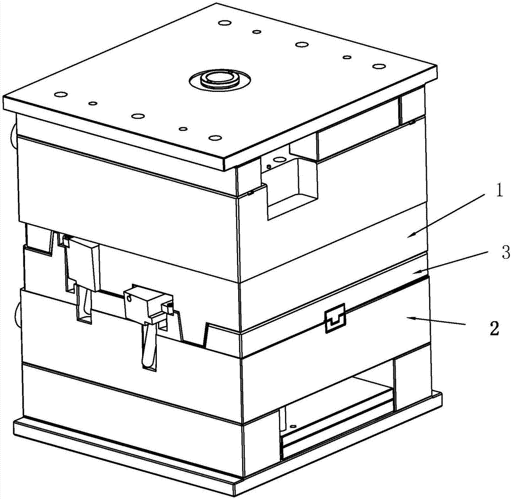
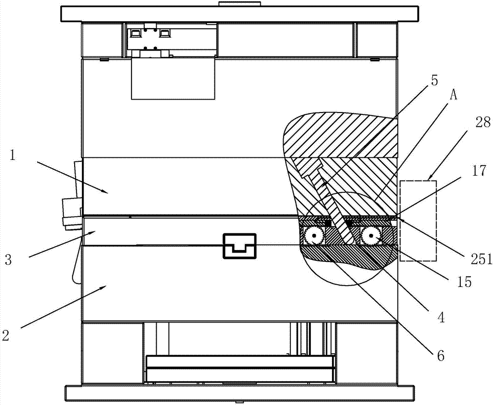
[0044] An injection mold, see figure 1 as well as figure 2 As shown in the figure, it includes a fixed mold 1 and a movable mold 2. The fixed mold 1 and the movable mold 2 can be close to or away from each other. A slider 3 is arranged between the movable mold 2 and the fixed mold 1, and the slider 3 slides. It is arranged on the side wall of the movable mold 2 close to the fixed mold 1. The mold opening and closing direction between the movable mold 2 and the fixed mold 1 is perpendicular to the sliding direction of the slider 3. The die 1 is connected with a toggle slant pin 5 that cooperates with the slanted hole 4. When the movable die 2 and the fixed die 1 are separated or approached, the toggle slant pin 5 will drive the slider 3 to slide left and right.

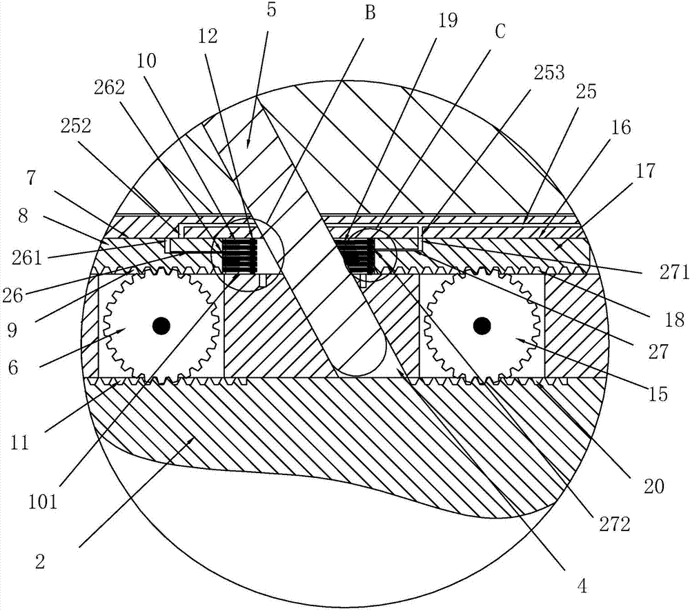
[0045] There are two main mechanisms in the slider 3:

[0046] The first part of the organizatio...


PUM


Abstract

The invention discloses an injection mold. According to the technical scheme, the injection mold is characterized by comprising a fixed mold and a movable mold; the side wall, close to the fixed mold, of the movable mold is provided with a sliding block in a sliding manner, the sliding block is provided with an oblique hole, and the fixed mold is connected with a stirring inclined pin matched with the oblique hole; the injection mold further comprises a first drive gear, the sliding block is internally provided with a first sliding groove communicating with the interior of the oblique hole, the first drive gear is rotationally connected to the sliding block, a first sliding cleaning block is arranged in the first sliding groove in a sliding manner, the side wall of the first sliding cleaning block is provided with a first sliding tooth face which can be engaged with the first drive gear, and the end portion of the first sliding cleaning block is provided with a first cleaning part used for making contact with the outer side wall of the stirring inclined pin; and the side wall, close to the fixed mold, of the movable mold is provided with a second drive tooth face used for being engaged with the first drive gear, the situation that as the first cleaning part abuts against the stirring inclined pin for a long time, early deformation occurs can be reduced through the internal structure, and the effective service life of the first cleaning part can be greatly prolonged while the cleaning effect is guaranteed.

Description

technical field [0001] The present invention relates to an injection mold. Background technique [0002] Injection mold is a tool for producing plastic products, and it is also a tool for imparting complete structure and precise dimensions to plastic products. Injection molding is a processing method used in mass production of certain parts with complex shapes. The injection molding machine injects high pressure into the mold cavity, and after cooling and solidifying, the molded product is obtained. [0003] The internal structure of the traditional two-color injection mold, such as the Chinese utility model with the announcement number CN201907173U, is a two-color injection mold, which includes a first-color injection mold and a second-color injection mold. After the first-color injection mold and the second-color injection mold. The mold is provided with a slider, the front mold of the second color injection mold is provided with a toggle pin, and the slider is provided w...

Claims


Application Information

Patent Timeline
IPC IPC(8): B29C45/33B29C45/17B29C45/83B29C33/72
CPCB29C45/1753B29C45/33B29C45/83
Inventor 李林杰
Owner 台州汇力普模塑有限公司
Features
  • R&D
  • Intellectual Property
  • Life Sciences
  • Materials
  • Tech Scout
  • Unparalleled Data Quality
  • Higher Quality Content
  • 60% Fewer Hallucinations
Learn More