Press stroke and die setting height adjusting mechanism

A technology of mold height and adjustment mechanism, applied in the field of presses, can solve the problems of unstable structure, easy failure, time-consuming and labor-intensive, etc., and achieve the effect of compact body layout and convenient adjustment

Active Publication Date: 2017-06-20
YANGLI GRP CORP LTD
View PDF7 Cites 8 Cited by
  • Summary
  • Abstract
  • Description
  • Claims
  • Application Information

AI Technical Summary

Problems solved by technology

When the mechanism works, the servo motor drives the crank to move, the crank drives the connecting rod to swing, the connecting rod drives the upper toggle to swing, the upper toggle drives the lower toggle to swing, and the lower toggle drives the slider to move up and down; its disadvantages are: The slider stroke and die height of the press cannot be adjusted, which cannot meet the requirements of different specifications of stamping dies and workpieces to be stamped, and the press has limitations.
The eccentricity of the eccentric sleeve of the device and the fixed eccentricity of the crankshaft are recombined to form another eccentricity, which changes the eccentricity of the crankshaft, thereby adjusting the slider stroke and die height of the press. The eccentric sleeve can only be rotated within a certain phase angle, the eccentricity of the crankshaft can only be changed within a certain range, and the stroke and stroke of the slider cannot be adjusted arbitrarily according to molds and workpieces of different specifications. The die height of the press still has limitations; manual operation to install the eccentric sleeve on the crankshaft is not convenient, time-consuming and laborious; the eccentric sleeve and the adjustment sleeve are connected by end teeth, the structure is unstable, and the torque formed by the rotation of the crankshaft The end teeth will be twisted off, which is prone to failure

Method used


Image

  • Press stroke and die setting height adjusting mechanism
  • Press stroke and die setting height adjusting mechanism
  • Press stroke and die setting height adjusting mechanism

Examples


Embodiment Construction

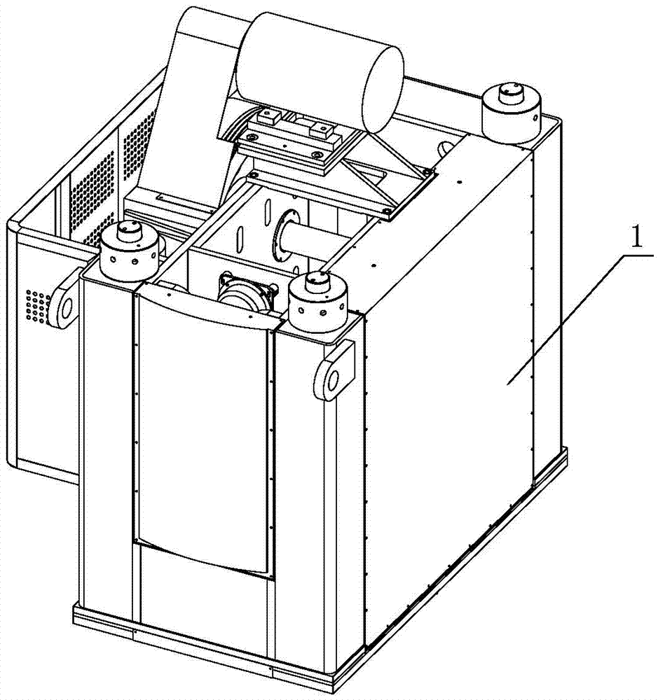
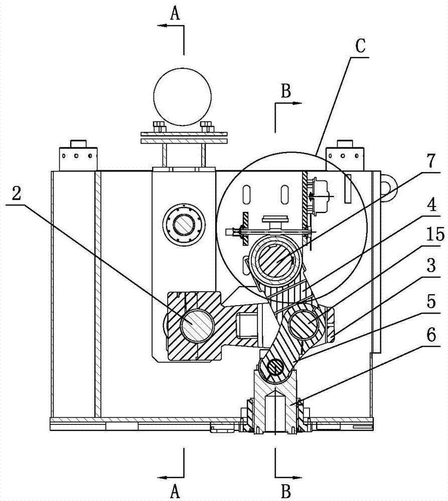
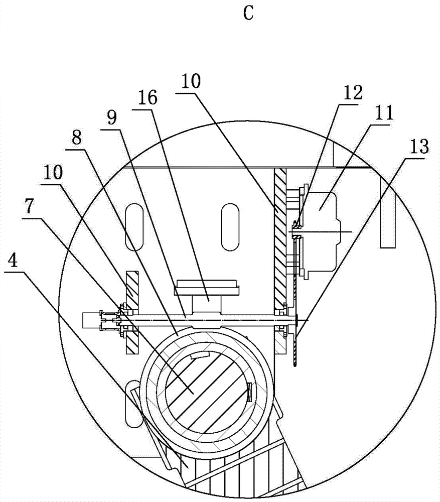
[0024] Such as Figure 1-10, is a press stroke and die height adjustment mechanism, including a fuselage beam 1, a rotatable crankshaft 2 is arranged horizontally on the fuselage beam 1, a connecting rod 3 is arranged on the connecting rod journal of the crankshaft 2, and a connecting rod The ends of 3 are respectively hinged with an upper toggle 4 and a lower toggle 5, and the lower end of the lower toggle 5 is hinged with a vertically movable guide post 6, and the lower end of the guide post 6 is provided with a slider. The toggle lever 4 is provided with a rotatable eccentric shaft 7, the eccentric shaft 7 is parallel to the rotation axis of the crankshaft 2, the upper end of the upper toggle lever 4 is fixedly connected with the eccentric section 701 of the eccentric shaft 7, and the main section of the eccentric shaft 7 is provided with a worm gear 8. A rotatable worm 9 is arranged on the beam 1 of the fuselage. The axis of the worm 9 is perpendicular to the rotation axis...


PUM


Abstract

The invention discloses a press stroke and die setting height adjusting mechanism in the field of presses. The press stroke and die setting height adjusting mechanism comprises a machine body cross beam. A rotatable crankshaft is horizontally arranged on the machine body cross beam. A connecting rod is arranged on the connecting rod journal of the crankshaft. An upper toggle rod and a lower toggle rod are hinged to the ends of the connecting rod correspondingly. A guide column which can vertically move is hinged to the lower end of the lower toggle rod. A sliding block is arranged at the lower end of the guide column. A rotatable eccentric shaft is arranged in the position, corresponding to the upper toggle rod, of the machine body cross beam and is parallel to the rotation axis of the crankshaft. The upper end of the upper toggle rod is fixedly connected with the eccentric section of the eccentric shaft. The main shaft section of the eccentric shaft is sleeved with a worm gear. The machine body cross beam is provided with a rotatable worm. The axis of the worm is perpendicular to the rotation axis of the eccentric shaft. The worm gear and the worm are engaged with each other. One end of the worm is in transmission connection with a rotary driving mechanism. The press stroke and die setting height adjusting mechanism can randomly adjust the press sliding block stroke and the die setting height, can automatically adapt to dies with different specifications and workpieces with different sizes, and is convenient to adjust and savable in time and effort.

Description

technical field [0001] The invention belongs to the field of presses, and in particular relates to a press stroke and die height adjustment mechanism. Background technique [0002] In the prior art, there is a triangular link-toggle link transmission mechanism with a high boost ratio for a servo press, its patent application number: 201010572167.7; application date: 2010.12.03; its structure includes a servo motor, an upper pin, an upper toggle, Triangular connecting rod, crank, middle pin shaft, lower toggle, unloading cylinder, and top piece cylinder. The output shaft of the servo motor is connected to the crank through the transmission mechanism to drive the crank to move. The crank is connected to the connecting rod to drive the connecting rod to swing. The rods are respectively connected with the upper toggle and the lower toggle, and the upper toggle is hinged and fixed on the fuselage, and the lower toggle is connected with the guide rail set by the fuselage through t...

Claims


Application Information

Patent Timeline
Patent Type & Authority Applications(China)
IPC IPC(8): B30B1/14B30B15/00B30B15/02
CPCB30B1/14B30B15/0029B30B15/026
Inventor 仲君黄建民阚翔严静芸吴连红张明路
Owner YANGLI GRP CORP LTD
Why Eureka
Try Eureka