Vehicle oil filling pipe
A technology for fuel injection pipes and automobiles, which is applied in the field of fuel injection pipes, which can solve the problems of fuel and fuel vapor easily gushing outwards, and achieve the effects of avoiding outward escape, reducing pressure, and extending the axial positioning length
- Summary
- Abstract
- Description
- Claims
- Application Information
AI Technical Summary
Problems solved by technology
Method used
Image

Examples
Embodiment 1
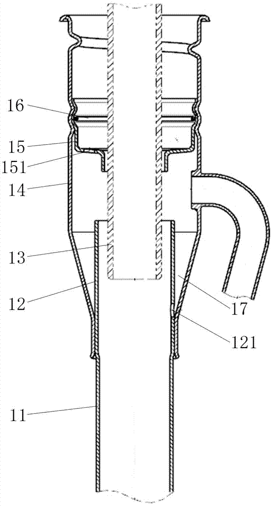
[0024] figure 1 The shown automobile oil filling pipe mainly includes an oil inlet pipe 11, a guide pipe 12, a connecting pipe 14, and a stopper sleeve 15 for the filling gun barrel. A guide pipe 12 for inserting the refueling gun barrel 13 is arranged below the stop sleeve 15 of the refueling gun barrel in 14 , and the lower part of the connecting pipe 14 is joined with the guide pipe 12 . The bottom of the filling gun barrel stopper 15 has a positioning jack matching with the filling gun barrel 3, and a ventilation hole 151 is provided on the filling gun barrel stopper 15 wall; the filling gun barrel stopper 15 is made of nylon material The stepped elastic thin-walled sleeve, the big end of the oiling gun barrel limit sleeve 15 is made into a bellows portion, and the connecting pipe 14 is also made with a corresponding bellows portion, the connecting pipe 14, the oiling gun barrel limit sleeve 15 The bellows parts of the two are fitted with each other, and an elastic ring 1...
Embodiment 2
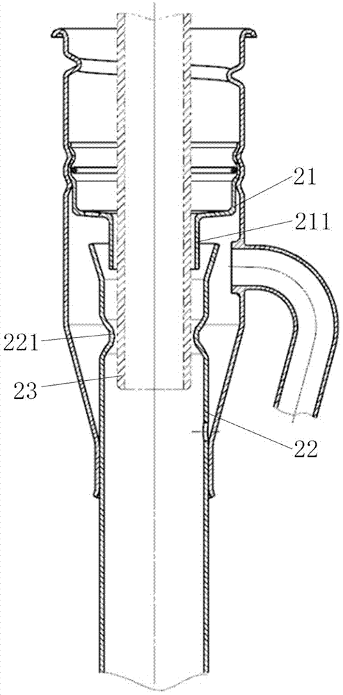
[0027] figure 2 In the shown automobile oil filling pipe, the small diameter section 211 of the stop sleeve 21 of the oil gun barrel is inserted into the guide pipe 22, and the mouth of the guide pipe 22 is provided with a bell mouth for easy assembly, and an inward convex ring 221 is arranged on the guide pipe 22, and other The embodiment can also be provided with several inwardly protruding bumps, which can further reduce the gap between the refueling gun barrel 23 and the guide tube 22, so that the parallelism between the two is better, and the rest of the features are the same as in the first embodiment. According to different fuel filling system designs, structural parameters such as the length of the guide pipe, the position of the protruding ring and the length of the positioning socket of the stop sleeve of the fueling gun barrel can be appropriately changed.
Embodiment 3
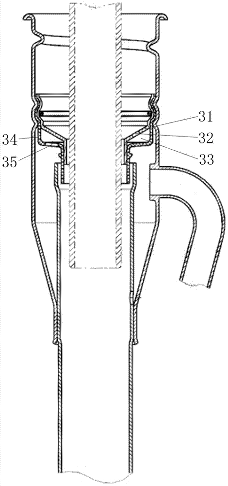
[0029] image 3 Shown automobile refueling pipe, there is an annular cavity 33 outside the positioning socket of the stop sleeve of the refueling gun barrel, and the upper cavity wall 31 of the annular cavity 33 is provided with an upper through hole 32, and the lower cavity wall of the annular cavity 33 34 is provided with a lower through hole 35, and the upper through hole 32 communicates with the lower through hole 35 through the annular cavity 33. The positions of the upper through hole 32 and the lower through hole 35 are staggered by a certain angle, and the staggered angle in this embodiment is 180°. All the other features are the same as in Example 2. When the remaining gasoline and fuel vapor comes to the annular cavity 33 of the stopper sleeve of the refueling gun barrel through the lower through hole 35, it will be limited by the cavity and can only perform swirling motion in the annular cavity 33. During this swirling process, the oil The kinetic energy of the vap...
PUM
 Abstract
Description
Claims
Application Information
 - R&D
- Intellectual Property
- Life Sciences
- Materials
- Tech Scout
- Unparalleled Data Quality
- Higher Quality Content
- 60% Fewer Hallucinations
Browse by: Latest US Patents, China's latest patents, Technical Efficacy Thesaurus, Application Domain, Technology Topic, Popular Technical Reports.
© 2025 PatSnap. All rights reserved.Legal|Privacy policy|Modern Slavery Act Transparency Statement|Sitemap|About US| Contact US: help@patsnap.com