

Dual-motor stepless variable speed vehicle power system
A continuously variable speed, power system technology, applied in electric power units, power units, vehicle components, etc., can solve the problem that the high-speed drive motor is not high enough at high speed, the transmission ratio is small, and the high-speed drive motor and low-speed drive motor work efficiency is low, etc. question
- Summary
- Abstract
- Description
- Claims
- Application Information
AI Technical Summary
Problems solved by technology
Method used
Image

Examples
Embodiment Construction
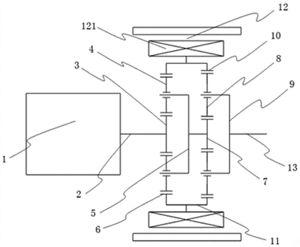
[0008] Preferred embodiments of the present invention will be described in detail below in conjunction with the accompanying drawings.
[0009] see figure 1 , the dual-motor continuously variable transmission vehicle power system of the present invention comprises a high-speed drive motor 1 comprising a high-speed motor shaft 2, a low-speed drive motor 12 comprising a low-speed motor rotor 121, and an output shaft 13, and its first sun gear 3 is located at the first Inside the planet carrier 5, the first planetary gear 4 is rotatably mounted on the first planet carrier 5, and the first ring gear 6 is located on the first planetary row outside the first planet carrier 5. The high-speed driving motor 1 The right end of the motor shaft 2 is fixedly connected with the first sun gear 3 of the first planetary row. Depend on figure 1 It can be seen that the present invention also includes an outer ring 11, and its second sun gear 7 is located inside the second planet carrier 9, the...
PUM
 Abstract
Description
Claims
Application Information