A Constraint-Guided Rail Vibration Damping Fastener Structure

A vibration-absorbing fastener and guide-type technology, applied in the direction of tracks, roads, fixed rails, etc., can solve the problems of interchangeability, poor versatility, large overall height of fasteners, difficulty in disassembling fasteners, etc., and achieve strong versatility , Efficient vibration reduction effect, convenient and quick removal effect

Active Publication Date: 2018-09-25
陕西长美科技有限责任公司 +1
View PDF6 Cites 0 Cited by
  • Summary
  • Abstract
  • Description
  • Claims
  • Application Information

AI Technical Summary

Problems solved by technology

The fastener has a relatively good vibration reduction effect, but it has many parts, complex structure, and poor reliability. Once it fails, it is difficult to disassemble the fastener. The entire fastener system needs to be removed when repairing and replacing the elastic pad under the plate; The height is significantly larger than that of ordinary fasteners, and the interchangeability and versatility are poor

Method used


Image

  • A Constraint-Guided Rail Vibration Damping Fastener Structure
  • A Constraint-Guided Rail Vibration Damping Fastener Structure
  • A Constraint-Guided Rail Vibration Damping Fastener Structure

Examples


Embodiment Construction

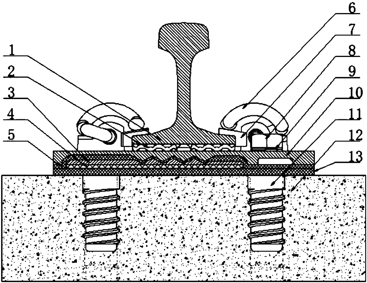
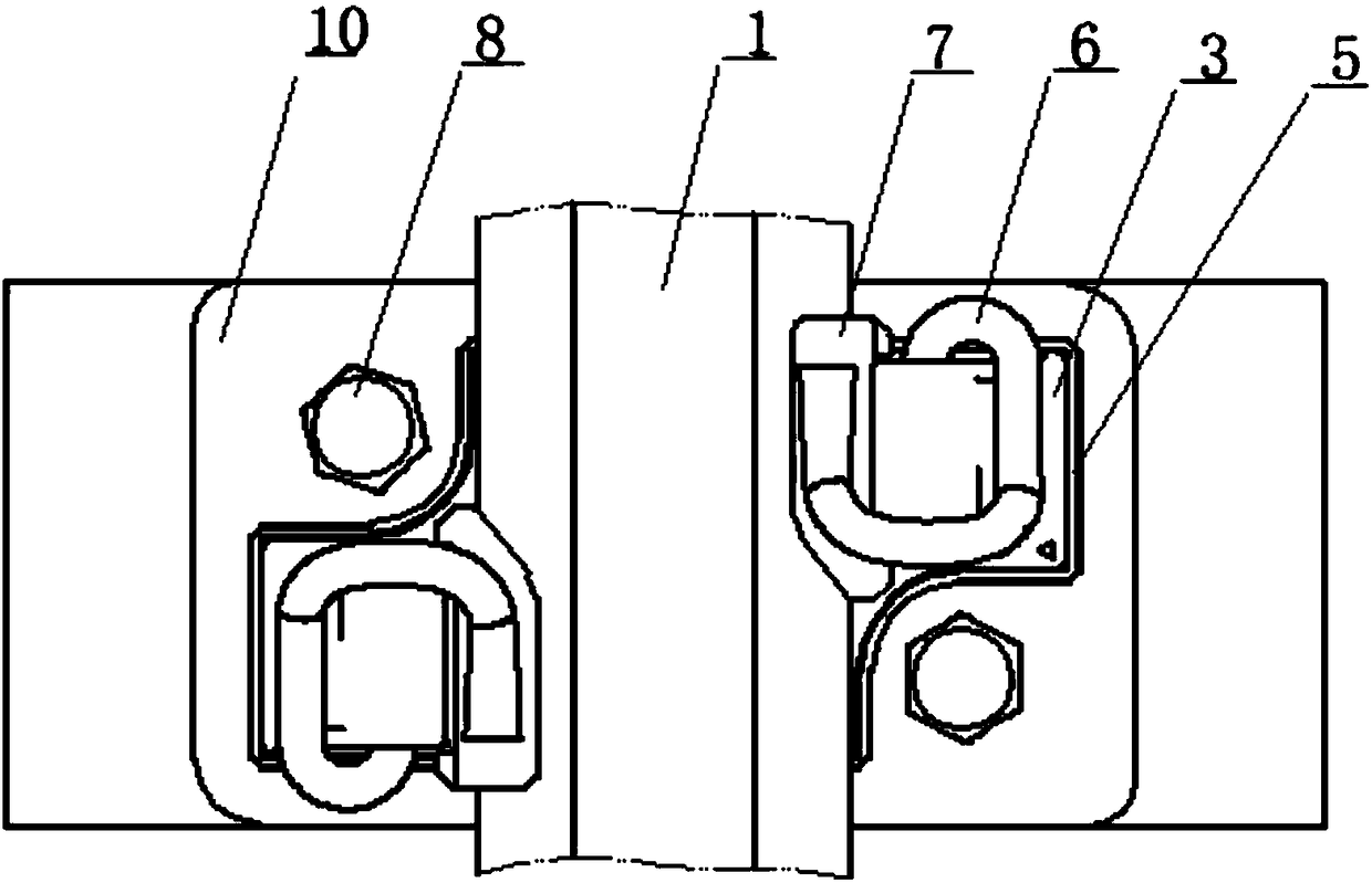
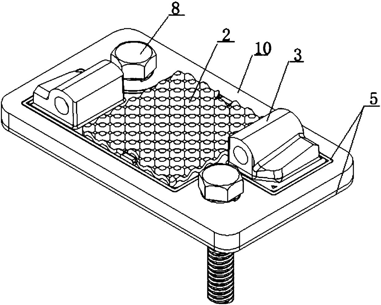
[0025] The following is attached Figure 1-7 An embodiment of the present invention is described.

[0026] A restraint-guided rail vibration-damping fastener structure, comprising an under-rail elastic backing plate 2, a rail-supporting iron backing plate 3, an under-board elastic backing plate 4, a constraint insulating sleeve 5, an elastic bar 6, a gauge pad 7, and a spiral track Nails 8, washers 9, outer frame constraint iron backing plate 10, embedded casing 11 and height adjustment backing plate 13; the height adjustment backing plate 13 is laid on the sleeper, and the elastic backing plate 4 under the board is laid on the height adjustment Backing plate 13. The upper surface of the elastic backing plate 4 under the plate has a positioning boss 17, and the lower surface of the rail iron backing plate 3 has a positioning groove 18 matching the positioning boss 17, and the positioning groove 18 is clamped on the On the positioning boss 17, and then the iron backing plate ...


PUM


Abstract

The invention discloses a constraint guiding type railway vibration damping fastener structure. An under-board elastic backing board of the structure is laid on a sleeper, and a rail bearing iron backing board is mounted on the upper surface of the under-board elastic backing board in a clamped mode. An annular spacer ring with the shape being matched with the shape of the outer contour of the middle of the rail bearing iron backing board is protruded from the upper surface of constraint insulation sleeve, and the rail bearing iron backing board is sleeved with the constraint insulation sleeve through the annular spacer ring. An outer frame constraint iron backing board is mounted above the constraint insulation sleeve in a clamped mode, and the inner contour of the outer frame constraint iron backing board is matched with the outer contour of the annular spacer ring. The outer frame constraint iron backing board, the constraint insulation sleeve, the rail bearing iron backing board and the under-board elastic backing board are levelly pressed on the sleeper or a track bed in a buckling mode through spiral track spikes, and the rail bearing iron backing board is constrained through the outer frame constraint iron backing board and the constraint insulation sleeve. An under-rail elastic backing board is placed on the upper surface of the rail bearing iron backing board, and a steel rail is laid on the under-rail elastic backing board. The steel rail is compressed on the under-rail elastic backing board through gauge cushions and elastic strips. Vibration and noise generated at the time of passing of a train can be effectively lowered, and taking comfort is improved.

Description

technical field [0001] The invention belongs to the technical field of rail transit fasteners, and in particular relates to a restraint-guided rail damping fastener structure. Background technique [0002] Fasteners are an important part of the track structure, which can fix the rail and ensure the accurate position of the rail, bear the load when the train passes, and resist the force transmitted from the wheel to the rail; at the same time, it can ensure the insulation and elasticity of the track. Reduce the vibration when the train passes and provide good ride comfort. With the development of society and the improvement of people's living standards, major cities have put forward higher requirements for the construction of urban rail transit, and many road sections need to take measures to reduce vibration and noise, which requires the fastener system to have high vibration reduction performance . [0003] The closest prior art to the present invention is a double-layer ...

Claims


Application Information

Patent Timeline
Patent Type & Authority Patents(China)
IPC IPC(8): E01B19/00E01B9/68
CPCE01B9/68E01B19/003
Inventor 张法明王红英杨保利尹菱菲陈刚闫玉锋田伟李晓云郑艳杨铁梅李强
Owner 陕西长美科技有限责任公司
Why Eureka
Try Eureka