
An electric high-temperature gate valve with a limit mechanism

A technology of high temperature gate valve and limit mechanism, which is applied to sliding valves, valve devices, mechanical equipment, etc., can solve the safety hazards of catalytic cracking devices, the inability of electric high temperature gate valves to open, and the valve plate wedge dead after clearance, so as to facilitate disassembly and sewage discharge. , The effect of preventing the valve plate from passing through and facilitating debugging and installation

Active Publication Date: 2019-05-07
BC P INC CHINA NAT PETROLEUM CORP +1
View PDF6 Cites 0 Cited by
  • Summary
  • Abstract
  • Description
  • Claims
  • Application Information

AI Technical Summary

Problems solved by technology

[0005] During the closing process of the valve plate, it is easy to cause the wedging of the valve plate, or the thermal expansion of the valve plate after closing may also easily cause the wedging of the valve plate, resulting in the failure of the electric high-temperature gate valve to open, causing a greater safety hazard to the catalytic cracking unit

Method used


Image

  • An electric high-temperature gate valve with a limit mechanism
  • An electric high-temperature gate valve with a limit mechanism

Examples


Embodiment Construction

[0039] In order to make the object, technical solution and advantages of the present invention clearer, the implementation manner of the present invention will be further described in detail below in conjunction with the accompanying drawings.

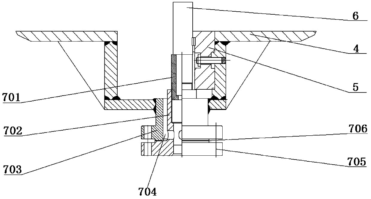
[0040] as attached figure 1 and attached figure 2 As shown, the embodiment of the present invention provides an electric high temperature gate valve with a limit mechanism, the electric high temperature gate valve includes: electric actuator 1, valve stem 2, valve cover 3, valve body 4, valve seat ring 5, valve plate 6. Further, the electric high-temperature gate valve also includes a limit mechanism 7, which includes a limit screw 701, a necked connection flange 702, and a necked condensation drain flange 703.

[0041] One end of the limit screw 701 abuts against the lower end of the valve plate 6 at the fully closed position, and the other end is threadedly connected to the neck of the neck flange 702 . The neck of the necked con...


PUM


Abstract

The invention discloses an electric high-temperature gate valve with a limiting mechanism, and belongs to the field of electric valves. The gate valve comprises an electric execution mechanism, a valve rod, a valve cover, a valve body, a valve seat ring, a valve plate and the limiting mechanism; the limiting mechanism comprises a limiting screw, a hubbed connecting flange and a hubbed condensate drainage flange; one end of the limiting screw abuts against the lower end of the valve plate located at the full-closed position, and the other end of the limiting screw is in threaded connection with the neck of the hubbed connecting flange; the neck of the hubbed condensate drainage flange is fixed to the end of the valve body, the neck of the hubbed connecting flange is installed inside a flange cavity of the hubbed condensate drainage flange in a sleeved mode, and a gap communicating with the external is formed between the neck of the hubbed connecting flange and the flange cavity of the hubbed condensate drainage flange and is used for draining condensate water in the valve body and preventing particulate matter from entering the valve body; and a blind flange of the hubbed connecting flange and a blind flange of the hubbed condensate drainage flange are in threaded connection through bolts, and a sealing gasket is arranged between the two blind flanges. According to the gate valve, the valve plate is prevented from being excessively closed, water and dirt can be discharged, and sediments in a valve cavity can be cleared conveniently.

Description

technical field [0001] The invention relates to the field of electric valves, in particular to an electric high-temperature gate valve with a limit mechanism. Background technique [0002] The electric high-temperature gate valve is a supporting control valve for the flue gas turbine in the catalytic cracking unit. It is usually installed on the inlet pipeline of the flue gas turbine, and the high-temperature flue gas containing catalyst particles is often used as a fluid medium, and is controlled by the electric high-temperature gate valve. Decide whether to pass. The opening and closing part of the electric high temperature gate valve is a valve plate, and the movement direction of the valve plate is perpendicular to the movement direction of the fluid medium. When the flue gas turbine is working normally, the valve plate is fully open. When the flue gas turbine needs to be shut down, the valve plate will automatically and quickly close to realize the self-protection chai...

Claims


Application Information

Patent Timeline
Patent Type & Authority Patents(China)
IPC IPC(8): F16K3/30F16K3/02
CPCF16K3/02F16K3/30
Inventor 张玉峰冯文魏奇刘晓东梁宗辉陈增辉胡安铎易捷秦启祥包彦平
Owner BC P INC CHINA NAT PETROLEUM CORP
Learn More