Thermal boiler

A boiler and thermal technology, applied in the field of thermal boilers, can solve the problems of large flue gas resistance horizontal rectangular reverse combustion boiler wall pressure, and achieve the effects of prolonging residence time, fully burning, and improving combustion efficiency

Pending Publication Date: 2017-06-20
王晓东
View PDF0 Cites 0 Cited by
  • Summary
  • Abstract
  • Description
  • Claims
  • Application Information

AI Technical Summary

Problems solved by technology

[0004] The invention relates to a thermal boiler, which solves the problem of relatively large flue gas resistance during combustion caused by the downward

Method used


Image

  • Thermal boiler
  • Thermal boiler

Examples


Embodiment Construction

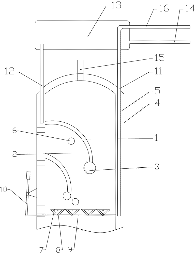
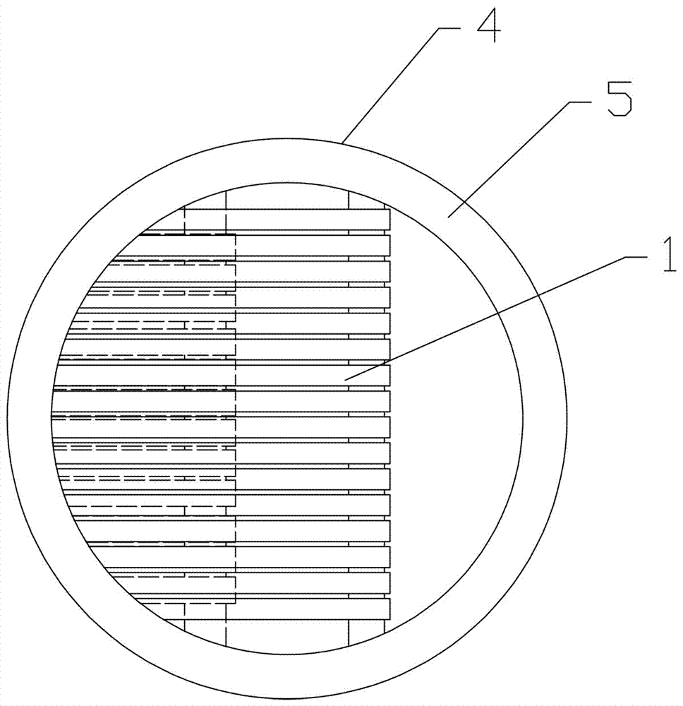
[0016] In the thermal boiler of the utility model, the furnace wall is a hollow water-circulating cavity. The furnace is provided with side-by-side elbows. The inner side of the side-by-side elbows and the furnace wall enclose at least one combustion chamber, and the upper part of the side-by-side elbow leads out from the furnace wall. , The side-by-side elbows are collected in the manifold at the lower part, and both sides of the manifold are opened into the furnace wall. The flame-retardant material is arranged between the side-by-side elbows to separate the upper and side of the combustion chamber from the upper part of the furnace. Fuel input ports are provided on both sides of the furnace wall and the front furnace wall.

[0017] In order to achieve the required combustion temperature in the boiler, only high combustion value fuel can be put in, and the suitable fuel is relatively single. By adopting the multi-combustion chamber structure of the present invention, it is poss...


PUM


Abstract

The invention relates to a thermal boiler, which belongs to boiler equipment. The technical scheme adopted in the present invention is: a thermal boiler, the furnace wall is a hollow water circulation inner cavity, and the furnace is provided with side-by-side elbows, at least one combustion chamber is enclosed between the inner side of the side-by-side elbows and the furnace wall, and the side-by-side elbows The upper part is drawn from the furnace wall, and the side-by-side elbows are collected in the confluence pipe at the lower part. The furnace walls on both sides and the front side of the combustion chamber are provided with fuel inlets.

Description

Technical field [0001] The invention relates to a thermal boiler, which belongs to boiler equipment. Background technique [0002] In the production of factories, especially those involving chemicals or food, hot water is required as raw material for production or as auxiliary heating. Hot water is usually used for heating in the north. [0003] For thermal boiler structures, there are vertical and horizontal rectangular structures. The opening of the combustion chamber of the common vertical reverse-fired cylindrical thermal boiler faces downwards to achieve the effect of saving coal. However, this kind of structure will result in a higher resistance to the flue gas in the burning state. There are hidden safety hazards in the pressure-bearing use of the furnace wall of the horizontal rectangular reverse-fired boiler. Summary of the invention [0004] The invention relates to a thermal boiler, which solves the problems of relatively large flue gas resistance during combustion ca...

Claims


Application Information

Patent Timeline
IPC IPC(8): F24H1/22F24H9/18
CPCF24H1/22F24H9/1845
Inventor 王晓东
Owner 王晓东
Why Eureka
Try Eureka