Novel flow-channel plate-fin type heat exchanger

A heat exchanger and plate-fin technology, applied in the field of heat exchangers, can solve problems such as unfavorable transportation and installation, heavy weight, and bulky heat exchangers, and achieve enhanced turbulent dissipation rate, increased turbulent dissipation rate, and improved The effect of turbulence properties

Inactive Publication Date: 2017-06-20
李晓波
View PDF0 Cites 1 Cited by
  • Summary
  • Abstract
  • Description
  • Claims
  • Application Information

AI Technical Summary

Problems solved by technology

Since the fin structure constituting the flow channel of the plate-fin heat exchanger is in the shape of a long sheet, in order to improve the heat exchange effect of the heat exchanger, the traditional fin structure needs to be improved. However, only from the thickness, height and heat transfer Although the improvement of the length of the flow channel in three aspects can increase the heat transfer capacity of the heat exchanger to a certain extent, the improved heat exchanger is not conducive to transportation and installation due to its bulky size and heavy weight.

Method used


Image

  • Novel flow-channel plate-fin type heat exchanger
  • Novel flow-channel plate-fin type heat exchanger

Examples


Embodiment Construction

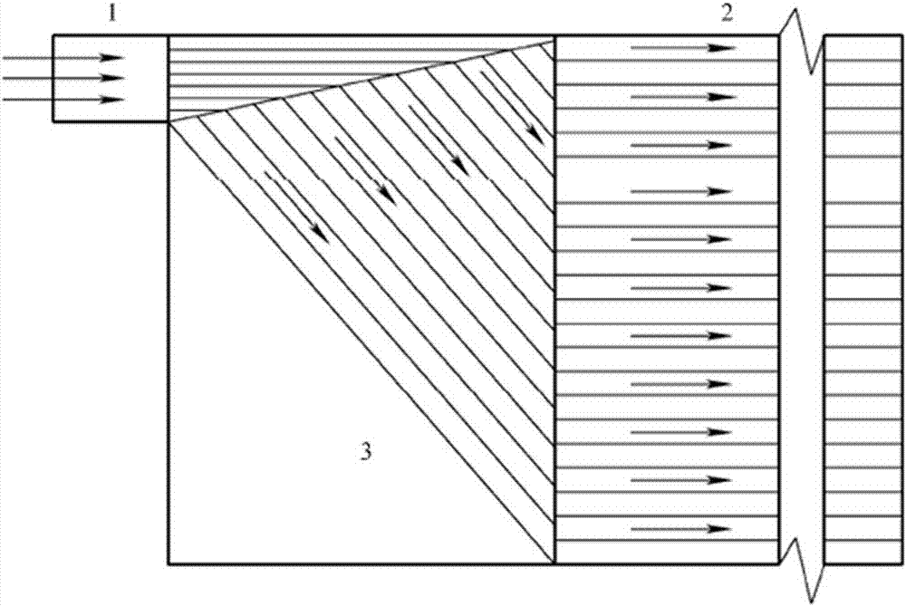
[0012] Preferably, the plate-fin heat exchanger unit mainly includes fins, baffles, deflectors, etc., and each unit is welded together by a vacuum brazing process, and the fluid flows in the flow channel formed by the fins.

[0013] exist figure 1 Among them, the plate-fin heat exchanger unit mainly includes fins, partitions, and deflectors. After each unit is welded together by vacuum brazing, the original fin type in the heat exchange section is replaced with a new type of fin. And there is no flow channel structure change in this heat exchange section.

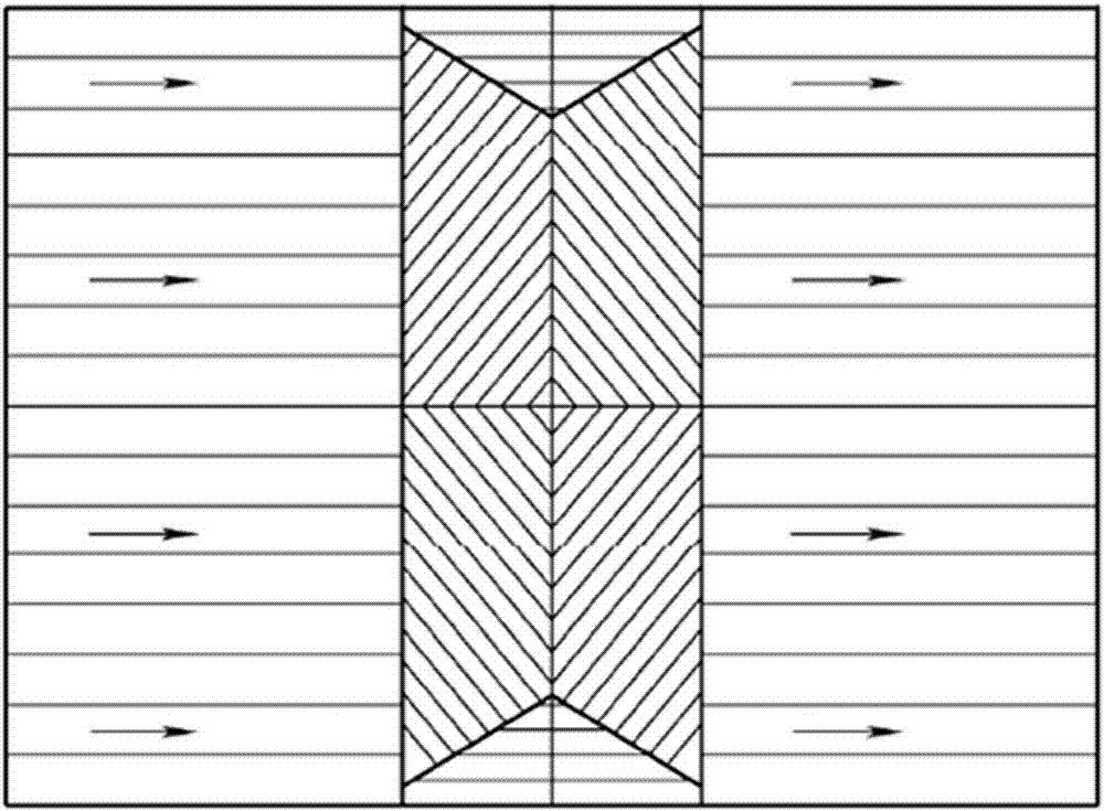
[0014] Preferably, on this basis, a new three-dimensional flow channel structure is adopted, such as figure 2 shown in .

[0015] exist figure 2 In the figure, the three-dimensional structure of the new flow channel is shown in the figure. In order to increase the turbulence performance of the fluid flow in the heat exchanger, extend the heat transfer distance, and improve the efficiency of the plate-fin heat exchanger...


PUM


Abstract

The new flow channel plate-fin heat exchanger adopts a new flow channel, mainly including fins, partitions, and deflectors. Each unit is welded together by vacuum brazing. The fin type in the heat exchange section mainly adopts new Fins, in order to make the pressure of the fluid inside the plate-fin heat exchanger higher than that of the traditional channel structure, to improve the fluid turbulence performance and the turbulent dissipation rate higher than the traditional structure, a new channel structure is adopted in the new channel structure Medium; due to the change of the channel structure, the turbulent dissipation rate of the fluid in the channel is greatly enhanced. Compared with the traditional channel structure, the average value of the turbulent dissipation rate at the inlet increases by 8.1 times, and the turbulent dissipation rate at other positions Both are greatly increased, and the heat dissipation effect is significantly improved.

Description

technical field [0001] The invention belongs to the technical field of heat exchangers, in particular to a plate-fin heat exchanger. Background technique [0002] Plate-fin heat exchangers usually consist of partitions, fins, seals, and deflectors. Fins, deflectors and seals are placed between two adjacent partitions to form an interlayer, which is called a channel. Such interlayers are stacked according to different fluid methods and brazed into a whole to form a plate bundle. The plate bundle is a plate. The core of the finned heat exchanger. Plate-fin heat exchanger has the advantages of compact structure, large specific surface area, high heat transfer efficiency, multi-stream heat exchange and secondary heat transfer, etc., so it has attracted more and more attention from experts and scholars at home and abroad. The fin is the main heat exchange unit of the plate-fin heat exchanger, and the flow channel structure formed by the fin plays a key role in the heat transfer...

Claims


Application Information

Patent Timeline
Patent Type & Authority Applications(China)
IPC IPC(8): F28D9/00F28F13/08
CPCF28D9/00F28F13/08
Inventor 李晓波
Owner 李晓波
Why Eureka
Try Eureka