Heat pipe with cross-section-variable upper header pipe

A heat pipe and upper set technology, applied in indirect heat exchangers, lighting and heating equipment, etc., can solve the problems of affecting the service life of heat pipes, affecting the efficiency of heat transfer, and low heat transfer coefficient, avoiding uneven temperature distribution, Long service life and uniform heat transfer

Active Publication Date: 2017-06-20
禹城京都新材料科技有限公司
View PDF4 Cites 23 Cited by
  • Summary
  • Abstract
  • Description
  • Claims
  • Application Information

AI Technical Summary

Problems solved by technology

[0004] The current heat pipe, especially the multi-pipe loop heat pipe, in the design, the upper condensation pipe is kept at the same height as the horizontal plane, such as figure 1 As shown, this design results in more heat exchange fluid in the middle of the upper header than at both ends, resulting in large heat transfer in the middle and small heat transfer at both ends, resulting in

Method used


Image

  • Heat pipe with cross-section-variable upper header pipe
  • Heat pipe with cross-section-variable upper header pipe
  • Heat pipe with cross-section-variable upper header pipe

Examples


Embodiment Construction

[0043] The specific embodiments of the present invention will be described in detail below in conjunction with the accompanying drawings.

[0044] In this article, if there is no special explanation, when it comes to formulas, " / " means division, and "×" and "*" mean multiplication.

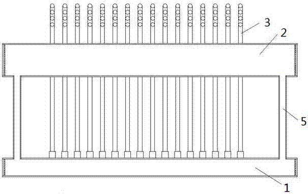
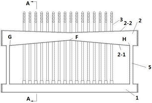
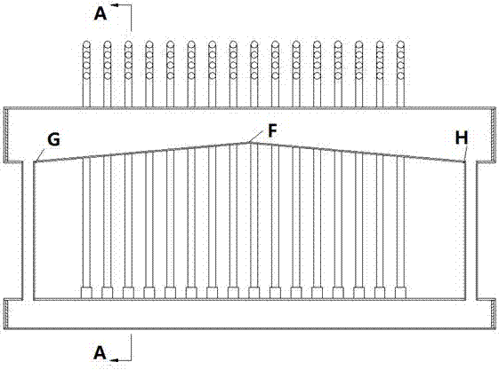
[0045] Such as figure 2 A heat pipe shown includes a lower header 1, an upper header 2, a riser 3 and a return pipe 5, the riser 2 communicates with the lower header 1 and the upper header 2, and the lower header 1 is the evaporation end, the condensation end includes at least a part of the upper header 2 and the riser 3, the fluid absorbs heat and evaporates in the lower header 1, and after exchanging heat with at least a part of the riser 3 and the upper header 2, Condensate in the upper header 1, and the condensed fluid returns to the lower header 1 through the return pipe 5; figure 2 As shown, from the middle of the upper header 2 (ie point F) to the two ends of the header 1 (ie points G,...


PUM


Abstract

The invention provides a heat pipe which comprises a lower header pipe, an upper header pipe, an ascending pipe and a return pipe, wherein the ascending pipe communicates with the lower header pipe and the upper header pipe; the lower header pipe is an evaporation end; a condensation end comprises the upper header pipe and at least part of the ascending pipe; fluid absorbs heat and evaporates in the lower header pipe and is condensed in the upper header pipe after heat exchange with at least part of the ascending pipe and the upper header pipe, and the condensed fluid returns to the lower header pipe through the return pipe; and cross section of the upper header pipe is gradually increased from the middle of the upper header pipe to the two ends of the upper header pipe. According to the invention, cross section of the upper header pipe is gradually increased from the middle of the upper header pipe to the two ends of the upper header pipe, so that heat exchanging fluid can be distributed to the two ends, heat exchange of the entire upper header pipe is ensured to be uniform, and nonuniformity of heat and temperature distribution of the upper header pipe is avoided to prolong the service life of the heat pipe.

Description

technical field [0001] The invention belongs to the field of heat pipes, in particular to a heat exchange heat pipe. Background technique [0002] Heat pipe technology is a heat transfer element called "heat pipe" invented by George Grover of Los Alamos National Laboratory in the United States in 1963. It makes full use of the principle of heat conduction and phase change medium. The rapid heat transfer properties of the heat pipe quickly transfer the heat of the heating object to the heat source, and its thermal conductivity exceeds that of any known metal. [0003] Heat pipe technology was widely used in aerospace, military and other industries before. Since it was introduced into the radiator manufacturing industry, people have changed the traditional radiator design ideas and got rid of the single heat dissipation mode that only relies on high air volume motors to obtain better heat dissipation. The use of heat pipe technology enables the radiator to obtain a satisfacto...

Claims


Application Information

Patent Timeline
IPC IPC(8): F28D15/02
CPCF28D15/0266
Inventor 于仁麟
Owner 禹城京都新材料科技有限公司
Why Eureka
Try Eureka