Circular police shield with guiding groove
A technology of guide grooves and police shields, applied in the direction of defenses, etc., can solve problems such as damage, throwing liquid splashes, etc., to avoid damage, slow down the sliding speed, and slow down the impact force.
- Summary
- Abstract
- Description
- Claims
- Application Information
AI Technical Summary
Problems solved by technology
Method used
Image
Examples
Embodiment 1
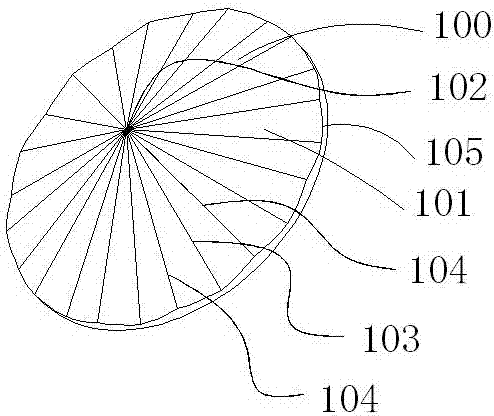
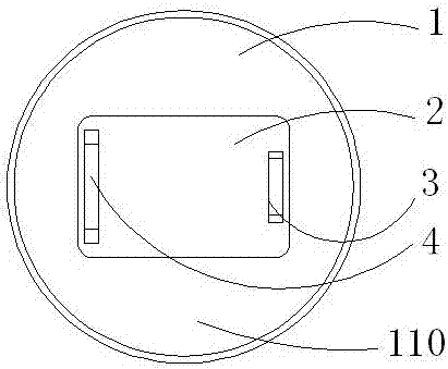
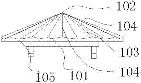
[0033] Embodiment 1: as Figure 1-4 As shown, a round police shield with a guide groove includes a shield body 1, a handle 4, a pad 2 and an elbow locking fixture 3, and the shield body 1 includes a shield body front 100 and a shield body back 140 , the pad 2 is connected to the shield body back 140, the handle 4 and the elbow locking fixture 3 pass through the pad 2 and are connected to the shield body 1, and the shield body front 100 includes an apex 102 , side edge 105 and guide groove 101, described side edge 105 forms the side of cylindrical shape, and described shield body front 100 is overall high in the middle, and has a low convex shape around, and described shield body front 100 can be a cone, or Approximate cone surface, the apex 102 is higher than the side 105, the guide groove 101 includes a land 104 and a valley 103, the land 104 and the valley 103 intersect at the apex 102, and the land 104 The height of the valley 103 decreases gradually from the apex 102 to t...
Embodiment 2
[0037] Such as Figure 4-6 As shown, this embodiment improves the protection device 5 on the basis of embodiment 1, wherein the protection device 5 further includes a second bending edge 502, a first bending edge 501 and a second bending edge The side 502 and the guide groove 101 form a U-shaped protection device. Another preferred technical solution, wherein, the top of the second bending edge 502 is provided with a barb, that is, a barb is provided on the U-shaped protective device.
[0038] Specifically, when encountering a projectile or liquid strike, the shield bearer adjusts the angle to meet the strike object, and after the strike object contacts the wrinkled surface formed by the guide groove 101, since the front surface of the shield body 100 is convex and the guide groove 101 is the apex One end of side 102 is high, and one end of side 105 is bottom, so due to the inertia of the hitting object, the hitting object will slide along the direction of guide groove 101, col...
Embodiment 3
[0040] Such as Figure 7-8 As shown, this embodiment improves the guide groove 101 on the shield body front 100 on the basis of Embodiment 1, and the same numbers in this embodiment represent the same structural features. The shield includes a shield body 1, a handle 4, a pad 2 and an elbow locking fixture 3, the shield body 1 includes a shield body front 200 and a shield body back 140, and the shield body 2 and the shield body The back side 140 is connected, the handle 4 and the elbow locking fixture 3 are connected to the shield body 1 through the pad 2, and the shield body front 200 includes an apex 202, a side edge 205 and a guide groove 201. The sides 205 form a cylindrical side, the shield body front 200 is generally high in the middle, and has a low convex shape around, the shield body front 200 can be a cone, or an approximate cone surface, and the apex 202 is higher than the The side 205, the guide groove 201 includes a land 204 and a valley 203, the land 204 and the...
PUM
 Abstract
Description
Claims
Application Information
 - R&D Engineer
- R&D Manager
- IP Professional
- Industry Leading Data Capabilities
- Powerful AI technology
- Patent DNA Extraction
Browse by: Latest US Patents, China's latest patents, Technical Efficacy Thesaurus, Application Domain, Technology Topic, Popular Technical Reports.
© 2024 PatSnap. All rights reserved.Legal|Privacy policy|Modern Slavery Act Transparency Statement|Sitemap|About US| Contact US: help@patsnap.com


