
Electric quantity measurement method, measuring circuit and method of calibration coefficient, and terminal device

A technology for calibrating coefficients and measuring circuits, which is applied in the electronic field, can solve problems such as inaccurate test results, circuit board damage, and impedance changes, and achieve the effects of avoiding impedance changes, ensuring calibration accuracy, and low design costs

Inactive Publication Date: 2017-06-20
SHANGHAI YUDE TECH CO LTD
View PDF4 Cites 5 Cited by
  • Summary
  • Abstract
  • Description
  • Claims
  • Application Information

AI Technical Summary

Problems solved by technology

[0004] However, in the process of realizing the present invention, the inventor finds that the following technical defects also exist in the prior art: 1. Welding test wires at both ends of the rated resistance will cause damage to the circuit board
2. It can only be debugged in the research and development stage, and cannot be imported into mass production
3. The rated resistance is usually a 10 milliohm resistor. Since the 10 milliohm resistor itself is a high-precision specification, welding the test wires at both ends of the 10 milliohm resistor will cause the impedance to change, making the test result inaccurate

Method used

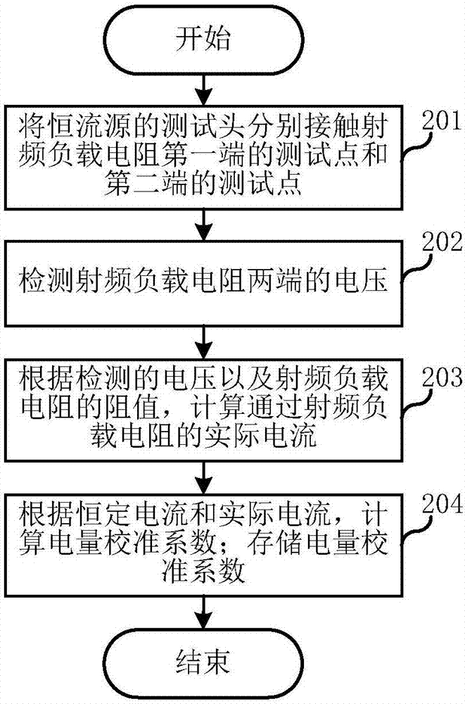
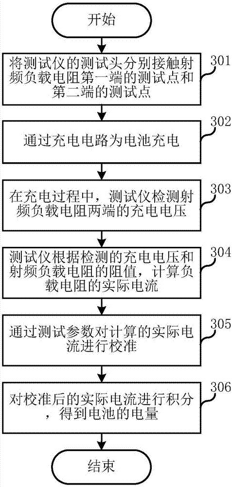

Image

  • Electric quantity measurement method, measuring circuit and method of calibration coefficient, and terminal device
  • Electric quantity measurement method, measuring circuit and method of calibration coefficient, and terminal device
  • Electric quantity measurement method, measuring circuit and method of calibration coefficient, and terminal device

Examples


Embodiment Construction

[0021] In order to make the object, technical solution and advantages of the present invention clearer, various embodiments of the present invention will be described in detail below in conjunction with the accompanying drawings. However, those of ordinary skill in the art can understand that, in each implementation manner of the present invention, many technical details are provided for readers to better understand the present application. However, even without these technical details and various changes and modifications based on the following implementation modes, the technical solution claimed in this application can also be realized.

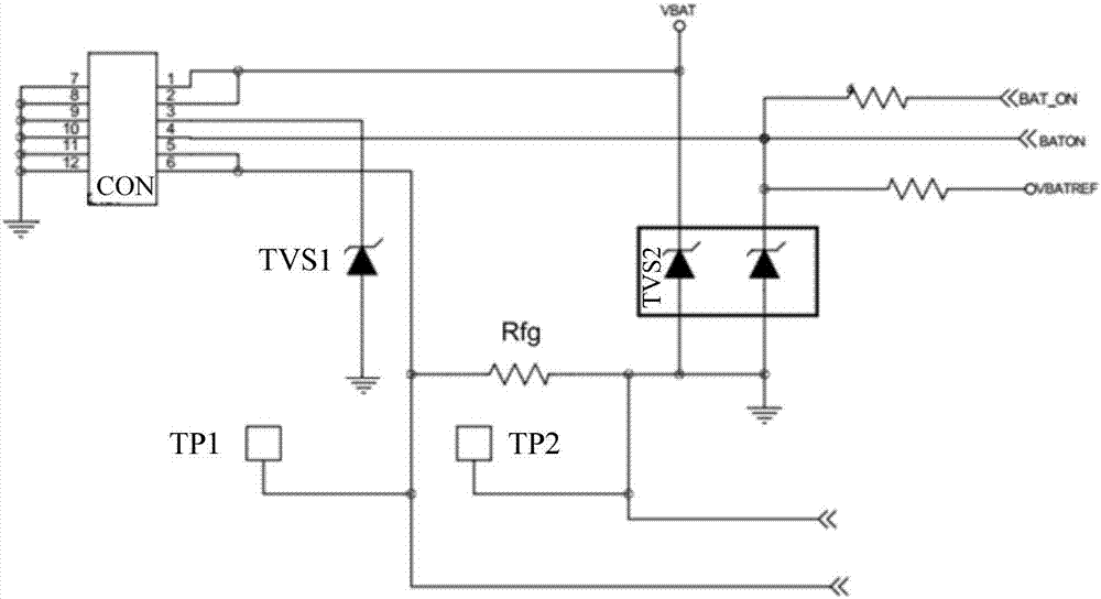
[0022] The first embodiment of the present invention relates to a measurement circuit of a power calibration coefficient. Such as figure 1 As shown, the measurement circuit of the power calibration coefficient includes: a fixed value resistor Rfg arranged on the circuit board and a battery connector CON; the first group of pins of the batt...


PUM


Abstract

The invention, which relates to the field of the electronic technology, discloses an electric quantity measurement method, a measuring circuit and method of a calibration coefficient, and a terminal device. The measuring circuit for an electric quantity calibration coefficient comprises a fixed-value resistor and a resistor connector that are arranged on the circuit board. A first pin group of the battery connector is connected with a positive electrode of a battery electrically; and a second pin group is connected with a negative electrode of the battery electrically. When the battery is connected to the battery connector electrically, a first end of the fixed-value resistor is connected with the negative electrode of the battery electrically by the second pin group and a second end of the fixed-value resistor is grounded. The first end and the second end enable test points arranged at the circuit board to be led out respectively; and the test points are used for contact with test heads of a constant-current source or a test instrument. Compared with the prior art, the measuring circuit enables the current flowing through the fixed-value resistor to be calibrated and the capacity of the battery to be tested, so that the damage to the circuit board can be avoided and the current calibration precision as well as the accuracy of the electric quantity testing result can be guaranteed.

Description

technical field [0001] The invention relates to the field of electronic technology, in particular to a power measurement method and a measurement circuit, method and terminal equipment of the calibration coefficient thereof. Background technique [0002] In recent years, with the continuous development of communication technology and the continuous advancement of science and technology, mobile terminals such as mobile phones, notebook computers, and tablet computers have become indispensable tools in people's daily life; this is because they are easy to carry, easy to use and give People's lives have brought great convenience. [0003] At present, testing the battery capacity of a mobile terminal to determine the performance of the battery is a necessary test that every manufacturer must carry out. Especially for batteries that can be recharged and used repeatedly, it is very necessary to strictly test their battery capacity and label them. When testing the battery capacit...

Claims


Application Information

Patent Timeline
Patent Type & Authority Applications(China)
IPC IPC(8): G01R19/00G01R31/36
CPCG01R19/0092G01R31/388
Inventor 李强郭洪瑾
Owner SHANGHAI YUDE TECH CO LTD
Learn More