Display panel, electronic device and test method

A technology for display panels and test pins, applied to circuits, electrical components, static indicators, etc., can solve the problem of inconvenient narrow frame design of display panels, and achieve the effect of facilitating narrow frame design and reducing width

Active Publication Date: 2017-06-20
WUHAN TIANMA MICRO ELECTRONICS CO LTD
View PDF13 Cites 35 Cited by
  • Summary
  • Abstract
  • Description
  • Claims
  • Application Information

AI Technical Summary

Problems solved by technology

In the existing display panel, it is necessary to separately set the signal line connecting the test pin and the test switch circuit in the frame area, so as to provide the test signal for the test switch circuit through the test pin, which is not convenient for the design of the narrow frame of the display panel

Method used


Image

  • Display panel, electronic device and test method
  • Display panel, electronic device and test method
  • Display panel, electronic device and test method

Examples


Embodiment Construction

[0032] The following will clearly and completely describe the technical solutions in the embodiments of the present invention with reference to the accompanying drawings in the embodiments of the present invention. Obviously, the described embodiments are only some, not all, embodiments of the present invention. Based on the embodiments of the present invention, all other embodiments obtained by persons of ordinary skill in the art without making creative efforts belong to the protection scope of the present invention.

[0033] In order to make the technical solutions provided by the embodiments of the present invention more clear, the above solutions will be described in detail below in conjunction with the accompanying drawings.

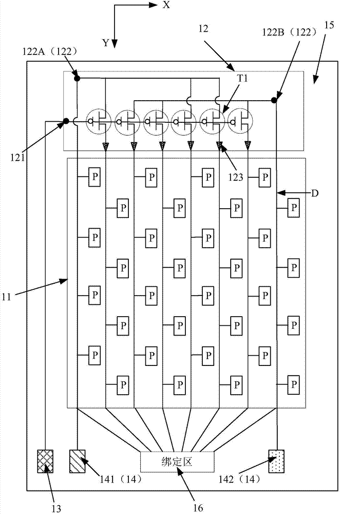
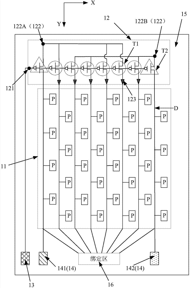
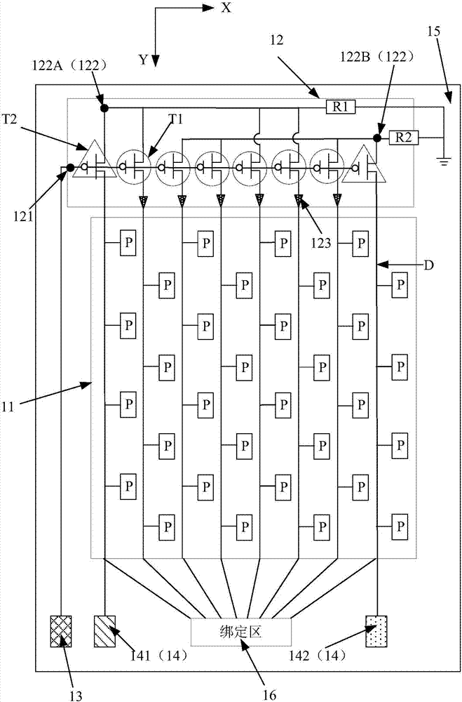
[0034] refer to Figure 1A , Figure 1A A schematic structural diagram of a display panel provided by an embodiment of the present invention, the display panel includes: a plurality of data lines D arranged in parallel, and the data lines D extend a...


PUM


Abstract

The invention discloses a display panel, an electronic device and a test method. The display panel comprises a plurality of data lines that are arranged parallel to each other and a display array, wherein the data lines extend in a first direction, the display array comprises a plurality of pixel units that are arranged in an array manner, the pixel units and the data lines are equal in quantity, and one line of pixel units are electrically connected with a data line correspondingly; in a first direction, a test switch circuit is arranged on one side of the display array, and driving lead pins and test lead pins are arranged on the other side of the display array; the test switch circuit has a control end, an input end and an output end; the driving lead pins are electrically connected with the control end, the driving lead pins are used for inputting switch control signals, the test lead pins are used for inputting test signals, the test lead pins are electrically connected with the input end via part of the data lines, and the rest of the data lines are connected with the output end. According to a technical solution of the display panel, the electronic device and the test method, the data lines are reused as signal lines for the test lead pins, and narrow frame design can be facilitated.

Description

technical field [0001] The present invention relates to the field of display technology, and more specifically, to a display panel, electronic equipment and a testing method. Background technique [0002] With the continuous development of science and technology, more and more electronic devices with display functions are widely used in people's daily life and work, which brings great convenience to people's daily life and work, and has become an indispensable essential tool. The display panel is the main component of electronic equipment to realize the display function. Among them, liquid crystal display panel and OLED display panel are two mainstream display panels in the display field today. In addition, display technologies such as micro LED display and quantum dot light-emitting diode display are also emerging. [0003] The display panel has a frame area and a display area, the display area has a display array, the display array has a plurality of pixel units arranged ...

Claims


Application Information

Patent Timeline
Patent Type & Authority Applications(China)
IPC IPC(8): G09G3/00G02F1/1362
CPCG02F1/1362G09G3/006G02F1/136254G02F1/1309G09G3/2092H10K59/131
Inventor 周井雄周瑞渊
Owner WUHAN TIANMA MICRO ELECTRONICS CO LTD
Why Eureka
Try Eureka