In-situ heating method of coal bed gas thermal exploitation

A technology of thermal mining and coalbed methane, which is applied in the direction of mining fluid, earthwork drilling, wellbore/well components, etc., and can solve problems such as difficult construction and impossibility of implementation

Active Publication Date: 2017-06-23
TAIYUAN UNIV OF TECH
View PDF6 Cites 21 Cited by
  • Summary
  • Abstract
  • Description
  • Claims
  • Application Information

AI Technical Summary

Problems solved by technology

[0007] The purpose of the present invention is to overcome the shortcomings of the prior art, provide an in-situ heating method for thermal mining of coalbed methane, and solve the problem that the existing mining method needs to carry out thermal insulation transformation and maintenance of the shaft, which brings great difficulties to the construction and in special areas. Technical issues that could not be implemented

Method used


Image

  • In-situ heating method of coal bed gas thermal exploitation
  • In-situ heating method of coal bed gas thermal exploitation

Examples


Embodiment 1

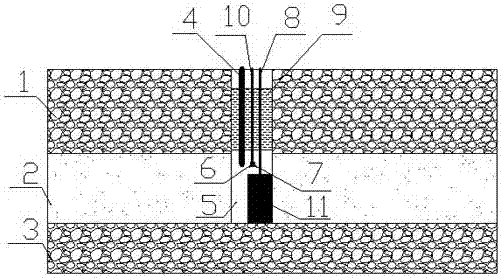
[0031] Such as figure 1 As shown, in a nearly horizontal single coal seam 2 with a thickness of 10m and a buried depth of 300m, the present invention is used to heat the coal seam in situ.

[0032] A method for in-situ heating of thermal mining of coalbed methane, the specific steps of which are as follows:

[0033] ① After hydraulic fracturing of the coal seam 2, vertical drilling 5 is carried out on the ground to the coal seam floor 3;

[0034] ② Place the electric heating rod 11 at the bottom of the well along the vertical drilling 5, and the electric heating rod 11 is connected to the ground with the No. 1 cable 8 sealed by a high-temperature-resistant rubber packer;

[0035] ③Arranging the water-injection steel pipe 4 with an inner diameter of 30-60 mm in the drilling well from the ground, so that the nozzle is in the middle of the coal seam at a position 1 / 2 to 2 / 3 of the thickness of the coal seam from the bottom of the coal seam;

[0036] ④ Place the temperature sens...

Embodiment 2

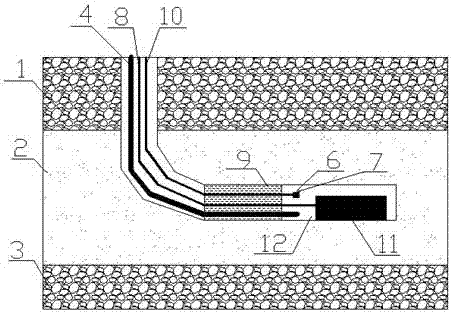
[0043] Such as figure 2 As shown, in a nearly horizontal single coal seam 2 with a thickness of 10m and a buried depth of 300m, the present invention is used to heat the coal seam in situ.

[0044] A method for in-situ heating of thermal mining of coalbed methane, the specific steps of which are as follows:

[0045] ① After hydraulic fracturing of coal seam 2, horizontal drilling 12 is carried out on the ground to the middle of the coal seam;

[0046] ② Place the electric heating rod 11 in the horizontal drilling along the horizontal drilling 12, and the electric heating rod 11 is connected to the ground with the No. 1 cable 8 sealed by a high-temperature resistant rubber packer;

[0047] ③ Arrange the water injection steel pipe 5 with an inner diameter of 30-60mm in the well from the ground, so that the nozzle is placed near the electric heating rod 11;

[0048] ④ Place the temperature sensor 6 and the pressure sensor 7 at the same position as the water injection steel pip...


PUM


Abstract

The invention relates to a coal bed gas thermal exploitation method, and particularly provides an in-situ heating method of coal bed gas thermal exploitation. The technical problems that in an existing exploitation method, a shaft needs to be subjected to improvement of heat insulation and maintenance, so that large difficulty is brought to construction and the method cannot be implemented in a special area are solved. The in-situ heating method comprises the steps that through drilling, a high-power electrical heating rod, a water injection steel tube and temperature and pressure sensors are placed in a coal bed gas reservoir which is subjected to hydraulic fracturing, blocking is conducted by means of high-temperature-resistant rubber packer, water is injected into a coal bed, the injected cold water is heated by means of the electrical heating rod, the water serves as a heat-transfer medium, thickness, permeability, gas content and other factors of the coal bed are combined, and the water injection rate of the coal bed and the heating power of the electrical heating rod are adjusted, so that the coal bed gas reservoir is heated in situ. The effective in-situ heating method is also provided for low-permeability coal bed gas thermal exploitation.

Description

technical field [0001] The invention relates to a method for thermal exploitation of coal bed gas. In particular, it relates to an in-situ heating method for thermal exploitation of coalbed methane, which heats the injected cold water by placing an electric heating rod in the coal reservoir, and uses the water as a heat transfer medium to realize heating of the coalbed. [0002] technical background [0003] Coal mine gas is a flammable gas. It is not only a precious resource, but also the biggest hidden danger that threatens the safe production of coal mines. During the mining process, gas diffuses from the coal seam and gushes out into the tunnel of the mine. When the gas concentration in the tunnel reaches the explosion limit and encounters an open flame, a coal mine gas explosion accident will occur. Underground gas pre-drainage in the coal seam or adjacent coal seams is an effective method to reduce mine gas emission and prevent coal mine gas disasters. The main extra...

Claims


Application Information

Patent Timeline
Patent Type & Authority Applications(China)
IPC IPC(8): E21B43/24E21B43/26
CPCE21B43/2401E21B43/2405
Inventor 周动孟巧荣冯增朝王辰郭纪哲赵阳升
Owner TAIYUAN UNIV OF TECH
Why Eureka
Try Eureka