Working device hinging mechanism

A technology of hinge mechanism and working device, applied in mechanical equipment, pivot connection, bearing components, etc., can solve problems such as poor dustproof effect, and achieve the effect of reducing impact, reducing processing cost, and enhancing circulation

Inactive Publication Date: 2017-06-23
LIUZHOU LIUGONG EXCAVATORS +2
View PDF5 Cites 1 Cited by
  • Summary
  • Abstract
  • Description
  • Claims
  • Application Information

AI Technical Summary

Problems solved by technology

[0004] The invention provides a hinge mechanism of a working device, which can solve the problem of poor dustproof effect of the hinge mechanism of the working device of the existing engineering machinery

Method used


Image

  • Working device hinging mechanism
  • Working device hinging mechanism
  • Working device hinging mechanism

Examples


Embodiment Construction

[0022] Below in conjunction with accompanying drawing example, the present invention is described in further detail:

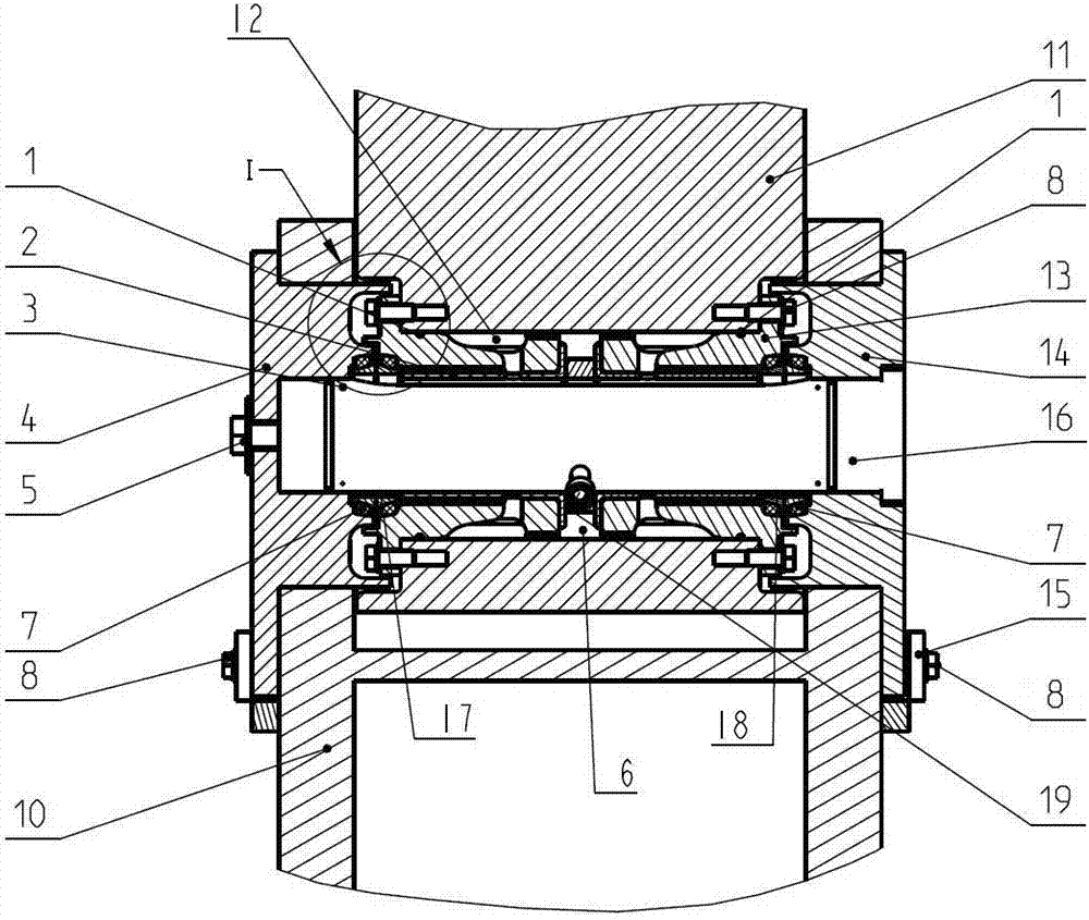
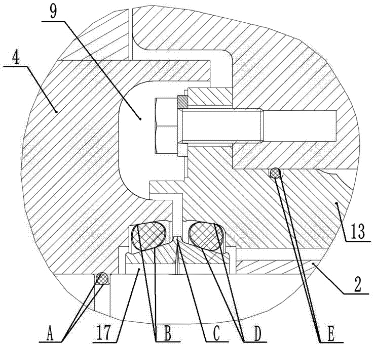
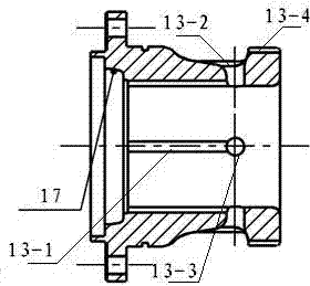
[0023] like figure 1 and Figure 5 In the shown embodiment, this embodiment is that the hinge mechanism is used in the assembly of the boom and the arm, the floating seal ring 7-1 and the sealing ring 7-2 form the floating oil seal 7, and two pairs of floating oil seals form a static sealing device , respectively installed on the inner surface of the end of the bushing 13 in contact with the inner end surface of the right floating seal seat 14, the second floating oil seal cavity 18, and the inner surface of the end head of the bushing 13 in contact with the inner end surface of the left floating seal seat 4 In the provided first floating oil seal cavity 17, the bushing 13 is fixed on the arm 11 by the bolt 8, so as to prevent the bushing 13 from rotating during the working process. The bearing bush 2 is press-fitted in the bushing 13, the shaft 16 passes th...


PUM


Abstract

The invention provides a working device hinging mechanism, and relates to the technical field of engineering machinery. The working device hinging mechanism comprises a bearing bush, a shaft and an anti-dust ring, wherein a bushing is arranged out of the bearing bush in a sleeving manner; the shaft is arranged in the bearing bush in a penetrating manner; a left floating sealing seat and a right floating sealing seat are respectively connected with the two ends of the shaft in a sleeving manner; a first floating oil sealing cavity is formed in a contact surface between the bushing and the left floating sealing seat; a second floating oil sealing cavity is formed in a contact surface between the bushing and the right left floating sealing seat; the first floating oil sealing cavity and the second floating oil sealing cavity are communicated with the shaft; a floating oil seal is arranged in each floating oil sealing cavity; a concave pit is formed in the inner end surface of each of the left floating sealing seat and the right floating sealing seat; end heads of the bushing are embedded into the concave pits; each embedding gap is a zigzag gap channel; compared with the prior art, the floating oil seals of the working device hinging mechanism form static seal; when the floating oil seals are in contact with each other and are rotated, dynamic end surface seal is formed; small particles do not enter the space between the shaft and a shaft sleeve easily, and an anti-dust effect is good; the adhesive wear and the abrasive wear of a bearing can be reduced; the work reliability of a sliding bearing mechanism can be improved.

Description

technical field [0001] The present invention is a divisional application of the patent application "Hinge Mechanism of Working Equipment". The application number of this patent application is 201410551997X, and the application date is October 17, 2014. The invention relates to the technical field of engineering machinery, in particular to a hinge mechanism of a working device. Background technique [0002] The connection between the working devices of construction machinery is generally connected by a sliding bearing hinge mechanism. Usually, the hinge mechanism is composed of a shaft, a bushing or a bearing bush, and a dustproof ring, and is lubricated by grease. However, the working conditions of construction machinery are harsh, and the distribution of working load is uneven, which may easily cause local stress on the shaft. In addition, the fluidity of the grease is poor, resulting in uneven local lubrication. Long-term work is likely to cause wear and failure of the sha...

Claims


Application Information

Patent Timeline
Patent Type & Authority Applications(China)
IPC IPC(8): F16C11/04F16C33/74F16C33/10
CPCF16C11/04F16C33/1055F16C33/1065F16C33/74
Inventor 李培冯豪石桂梅刘剑白容刑树鑫李德兴赵锋张影
Owner LIUZHOU LIUGONG EXCAVATORS
Why Eureka
Try Eureka