Rotary type annular soil-bin test platform braking mechanism

A technology of annular soil tank and braking mechanism, which is applied in the direction of brake actuator, brake type, axial brake, etc., and can solve the problems of inability to brake and stop the rotation of the ring soil tank, low use efficiency, long stop time, etc. problems, to achieve the effect of improving equipment use efficiency, avoiding losses and injuries, and braking quickly and reliably

Active Publication Date: 2017-06-23
HEILONGJIANG PROV AGRI MACHINERY ENG SCI INST
View PDF7 Cites 2 Cited by
  • Summary
  • Abstract
  • Description
  • Claims
  • Application Information

AI Technical Summary

Problems solved by technology

However, since the existing rotating annular soil tank test bench is not equipped with a braking mechanism to stop the rotation of the circular soil tank, it is found in the practice of scientific research and experiment that after the test bench works, it relies on slowly reducing the frequency conversion speed regulating motor. Frequency, by reducing the number of revolutions of the variable frequency speed regulating motor to drive the annular soil tank to decelerate until it stops rotating, the time of stopping is long and the use efficiency is low
Especially when the emergency stop of the test bench is required, the rotation of the annular soil tank cannot be braked, resulting in accidents

Method used


Image

  • Rotary type annular soil-bin test platform braking mechanism
  • Rotary type annular soil-bin test platform braking mechanism
  • Rotary type annular soil-bin test platform braking mechanism

Examples


Embodiment Construction

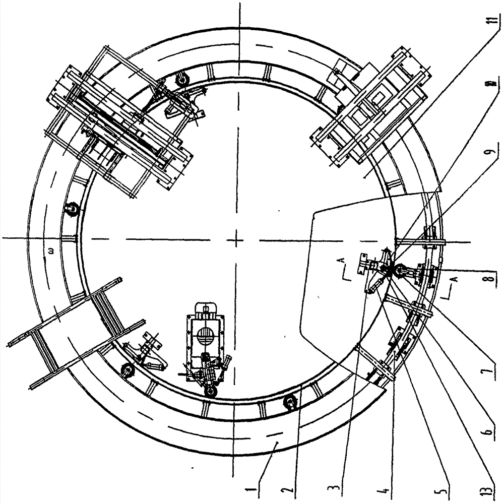
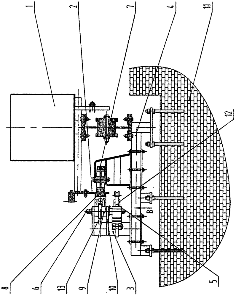
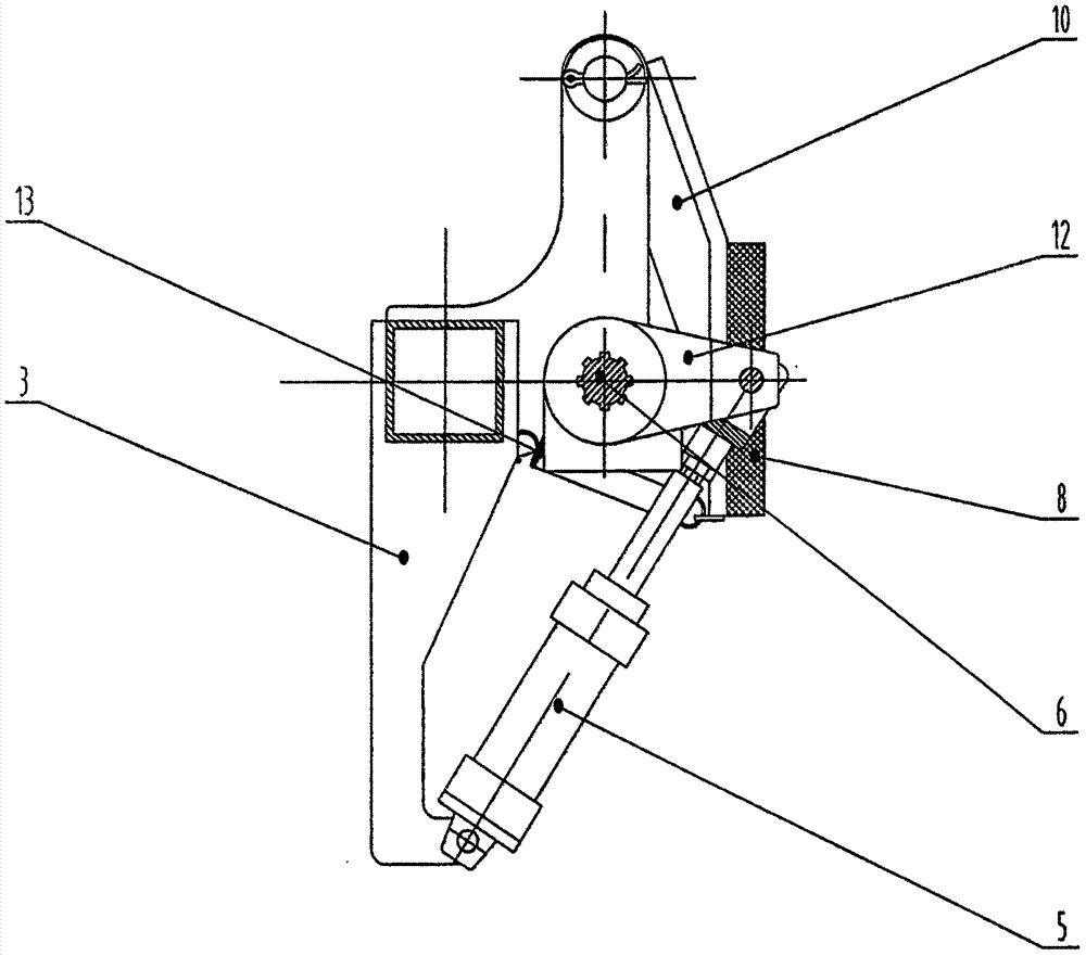
[0011] Embodiments of the present invention will be described in detail below in conjunction with the accompanying drawings. A rotary annular soil tank test bench braking mechanism, on the base 11, the ring-shaped soil tank 1 can be rotatably installed through the ring track frame 4, and the inner ring gear and the cylindrical cylinder are fixed on the inner wall surface of the ring-shaped soil tank 1 The assembly 2 is equipped with a center positioning support wheel 7 on the annular track frame 4 at the outer part of the circumference of the ring gear and cylinder combination 2, and the center positioning support wheel 7 is combined with the ring gear and the cylinder The outer wall surface of the body 2 is in a contact fit, and the brake frame 3 is fixed on the annular track frame 4, which is located at the inner side of the inner ring gear and the cylinder assembly 2 and the opposite position of the central positioning support wheel 7. The brake drive cylinder 5 and the fri...


PUM


Abstract

The invention discloses a rotary type annular soil-bin test platform braking mechanism which belongs to scientific research and test equipment. A braking mechanism rack is fixedly arranged at a part, which is located on the inner side of the periphery of an inner gear ring and cylinder combined body and is opposite to a center locating supporting wheel, on an annular rail rack; a braking driving cylinder and a friction plate seat are hinged to the braking mechanism rack; a driving shaft is inserted into the braking mechanism rack; a driving arm and a braking cam are fixedly arranged on the driving shaft; the driving arm is hinged to the braking driving cylinder; the braking cam is in contact matching with the friction plate seat; the two ends of a return tension spring are connected with the braking mechanism rack and the friction plate seat respectively; and a braking friction plate is fixedly arranged on the friction plate seat, and is in contact matching or disengagement contact matching with the inner wall surface of a cylinder of the inner gear ring and cylinder combined body. The rotary type annular soil-bin test platform braking mechanism can quickly and reliably brake a rotating annular soil-bin to allow the annular soil-bin to stop rotating, and has the advantages that the structure is novel and reasonable, unexpected accidents are avoided in a test, the test safety is ensured and the test efficiency is improved.

Description

technical field [0001] The invention belongs to scientific research and test equipment, and mainly relates to a braking mechanism of a rotating annular soil tank test bench for the test of agricultural machinery operating parts. Background technique [0002] Based on the characteristics of small footprint, compact equipment, high test efficiency, low manufacturing cost, and wide application range, the rotary annular soil tank test equipment has been widely used in the scientific research of agricultural machinery. The maturity of scientific and technological achievements has played a positive role in safeguarding. However, since the existing rotating annular soil tank test bench is not equipped with a braking mechanism to stop the rotation of the circular soil tank, it is found in the practice of scientific research and experiment that after the test bench works, it relies on slowly reducing the frequency conversion speed regulating motor. Frequency, by reducing the number ...

Claims


Application Information

Patent Timeline
Patent Type & Authority Applications(China)
IPC IPC(8): F16D65/18F16D55/22
CPCF16D55/22F16D65/18
Inventor 马君蔡晓华吴泽全孙先明程睿赵毅王伟于磊王恒一
Owner HEILONGJIANG PROV AGRI MACHINERY ENG SCI INST
Why Eureka
Try Eureka