Self-cleaning oil-collecting box for elevator

An oil collecting box and self-cleaning technology, applied in lubricating oil containers, engine components, elevators, etc., can solve the problems of secondary pollution of lubricating oil in the oil collecting box, corrosion and damage of elevator equipment, and pollution of the internal environment of elevator shafts, etc. Ensure continuity and stability, flexible and convenient installation and use, and avoid secondary pollution

Inactive Publication Date: 2017-06-23
SHANGHAI ZHONGDIAN TECH CO LTD
View PDF0 Cites 5 Cited by
  • Summary
  • Abstract
  • Description
  • Claims
  • Application Information

AI Technical Summary

Problems solved by technology

[0002] In order to improve the stability of the elevator operation, it is often necessary to apply continuous lubricating oil to the guide rails and other structures of the elevator. Although this method can effectively lubricate the elevator structure fully and effectively, it also causes a large amount of lubricating oil to accumulate at the bottom of the elevator shaft, which seriously pollutes the internal environment of the elevator shaft on the one hand, and on the other hand, a large amount of accumulated lubricating oil It will cause corrosion damage to the elevator equipment, thus seriously threatening the safety of elevator operation. To solve this problem, the current main method is to install an oil collection box at the bottom of the elevator guide rail, and collect the lubricating oil on the guide rail through the oil collection box. However, the current The oil collection box often only has the ability to collect lubricating oil, but does not have the ability to process the collected lubricating oil. On the one hand, the oil collection box needs to be cleaned manually on a regular basis, which increases the workload and cost of elevator maintenance and management. On the other hand, it is also easy to cause secondary pollution of the lubricating oil in the oil collection box due to dust, etc. Therefore, in view of this situation, it is urgent to develop an inventive oil collection box for elevators to meet the needs of actual use.

Method used


Image

  • Self-cleaning oil-collecting box for elevator

Examples


Embodiment Construction

[0014] In order to make the technical means, creative features, goals and effects achieved by the present invention easy to understand, the present invention will be further described below in conjunction with specific embodiments.

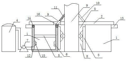
[0015] Such as figure 1 The described self-cleaning elevator oil collection box includes a box body 1, a box cover 2, a positioning seat 3, an oil storage tank 4, a filter device 5, a heating device 6 and a return pump 7, wherein at least one surface of the box body 1 A connection groove 8 is established, and the positioning seat 3 is installed on the outer surface of the connection groove 8 of the box body 1, and is slidably connected with the elevator guide rail 9. The box cover 2 is installed on the upper surface of the box body 1, and the top of the box body 1 is in contact with the elevator guide rail 9. A deflector 10 is arranged on the side surface, and one end of the deflector 10 is hinged with the box body 1, and the other end is offset a...


PUM


Abstract

The invention relates to a self-cleaning elevator oil collection box, which includes a box body, a box cover, a positioning seat, an oil storage tank, a filter device, a heating device and a return pump, wherein at least one surface of the box body is provided with a connecting groove, and the positioning seat is additionally installed On the outer surface of the connecting groove of the box body and slidingly connected with the elevator guide rail, the box cover is installed on the upper surface of the box body, and a deflector is arranged on the side surface of the top of the box body in contact with the elevator guide rail, and one end of the deflector plate is hinged to the box body , the other end is against the guide rail of the elevator, and a sewage outlet is provided at the bottom of the box body, and it is connected with the oil storage tank through the sewage outlet. . On the one hand, the present invention can effectively collect excess lubricating oil and oil stains generated on the guide rails of the elevator, and on the other hand, it can automatically clean the lubricating oil stored inside the oil collecting box according to the needs of use, thereby ensuring that the oil collecting box Continuity and stability of operation.

Description

technical field [0001] The invention relates to an elevator lubricating device, in particular to a self-cleaning elevator oil collecting box. Background technique [0002] In order to improve the stability of the elevator operation, it is often necessary to apply continuous lubricating oil to the guide rails and other structures of the elevator. Although this method can effectively lubricate the elevator structure fully and effectively, it also causes a large amount of lubricating oil to accumulate at the bottom of the elevator shaft, which seriously pollutes the internal environment of the elevator shaft on the one hand, and on the other hand, a large amount of accumulated lubricating oil It will cause corrosion damage to the elevator equipment, thus seriously threatening the safety of elevator operation. To solve this problem, the current main method is to install an oil collection box at the bottom of the elevator guide rail, and collect the lubricating oil on the guide r...

Claims


Application Information

Patent Timeline
Patent Type & Authority Applications(China)
IPC IPC(8): F16N31/02F16N39/06F16N39/04F16N19/00B66B7/12
CPCF16N31/02B66B7/1269F16N19/00F16N39/04F16N39/06
Inventor 吴明晖
Owner SHANGHAI ZHONGDIAN TECH CO LTD
Why Eureka
Try Eureka