
CBCT image ring-like false shadow removing method

A ring artifact and image projection technology, which is applied in image enhancement, image analysis, image data processing, etc., can solve the problems of new interpolation artifacts, loss of area information near metal and bone information, etc., and achieve the goal of reducing stripe artifacts Effect

Inactive Publication Date: 2017-06-23
JIANGSU MEILUN IMAGING SYST
View PDF3 Cites 10 Cited by
  • Summary
  • Abstract
  • Description
  • Claims
  • Application Information

AI Technical Summary

Problems solved by technology

[0008] The purpose of the present invention is to provide a method for removing ring artifacts in CBCT images, which can not only effectively solve the problem that the interpolation method will bring new artifacts, but also solve the problem that the interpolation method will cause the loss of information in the area near the metal and bone information

Method used


Image

  • CBCT image ring-like false shadow removing method
  • CBCT image ring-like false shadow removing method
  • CBCT image ring-like false shadow removing method

Examples


Embodiment 1

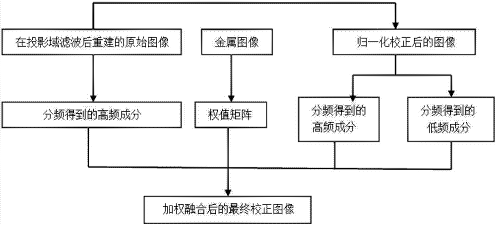
[0031] see figure 1 Shown, a kind of CBCT image ring artifact removal method comprises the following steps:

[0032] Step 1. Preprocessing the collected original data through full variation adaptive filtering, and then reconstructing the original image containing metal artifacts;

[0033] Step 2, segmenting the original image to obtain a metal image;

[0034] Step 3, performing intensity smoothness low-pass filtering on the metal image and normalizing to obtain a weight matrix;

[0035] Step 4, performing frequency division processing on the original image to obtain the high frequency part of the original image;

[0036] Step 5, performing normalization correction processing on the original image to obtain a corrected image;

[0037] Step 6, performing frequency division processing on the corrected image to obtain a high-frequency part and a low-frequency part of the corrected image;

[0038] Step 7: Perform weighted fusion of the high-frequency part of the original image,...

Embodiment 2

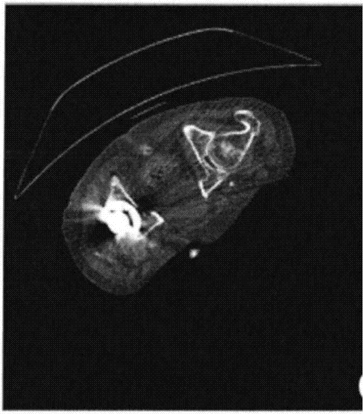
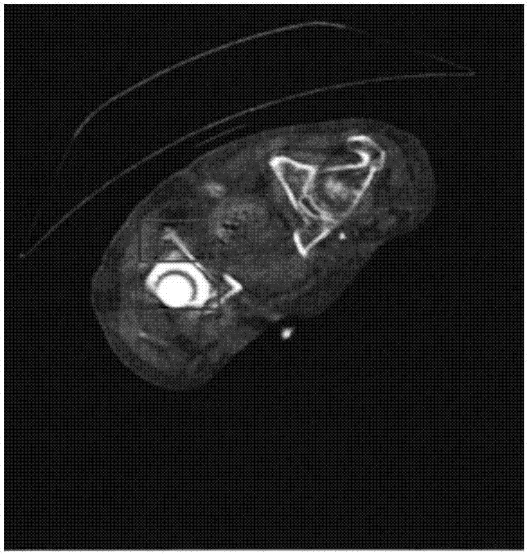
[0049] The validity and reliability of the ring artifact removal algorithm of the present invention are verified by measured data, specifically, the scanning parameters are 120kV, the layer thickness is 0.6mm, the reconstruction FOV is 500mm, and the image size of the filtered back projection reconstruction is 512×512, For comparison before and after ring artifact removal, see figure 2 with 3 As shown, it can be seen that image 3 Clear edge information and structure information are restored in the method, and the present invention can completely remove metal artifacts while retaining more detail information of the metal region.

[0050] Therefore, the present invention has achieved very good results in the removal of metal artifacts, and has great practical value for clinical diagnosis applications. Calibration method.


PUM


Abstract

The invention discloses a CBCT image ring-like false shadow removing method. The method comprises the following steps of preprocessing collected original data and then reconstructing an original image; segmenting the original image so as to acquire a metal image; carrying out low-pass filtering of strength smoothness and normalization on the metal image so as to acquire a weight matrix; carrying out frequency division processing on the original image so as to acquire a high-frequency portion of the original image; carrying out normalized correction processing on the original image so as to acquire a corrected image; carrying out frequency division processing on the corrected image so as to acquire a high-frequency portion and a low-frequency portion of the corrected image; carrying out weight fusion on the high-frequency portion of the original image, the weight matrix, and the high-frequency portion and the low-frequency portion of the corrected image so as to acquire a final corrected image. A problem that an interpolation method can bring a new false shadow can be effectively solved and a problem that the interpolation method can cause nearby metal area information and skeleton information losses can also be solved.

Description

technical field [0001] The invention relates to the field of medical instrument imaging, in particular to a method for removing ring artifacts in CBCT images. Background technique [0002] In recent years, cone-beam computed tomography (Cone-beam Computed Tomography) has been widely used in medical fields such as clinical diagnosis and 3D implants. As a type of tomography, cone-beam CT has many advantages such as accurate imaging and high utilization of rays. However, due to limitations of multiple factors such as system technology, design, and reconstruction methods, there are often a series of concentric rings with the reconstruction center as the center and gray values ​​that are different from surrounding pixels in cone-beam CT images, that is, ring artifacts. The appearance of ring artifact seriously affects the quality and authenticity of the image, and interferes with further clinical diagnosis and treatment. Therefore, how to remove the ring artifact without affect...

Claims


Application Information

Patent Timeline
IPC IPC(8): G06T5/00G06K9/62
CPCG06T2207/10081G06F18/23213G06T5/70
Inventor 王燕妮
Owner JIANGSU MEILUN IMAGING SYST
Learn More