Wireless charger employing H bridge and multivibrator

A technology of multivibrator and wireless charger, applied in current collectors, electric vehicles, electrical components, etc., can solve the problem of messy wires in manual operation, and achieve the effect of high efficiency and high power transmission

Inactive Publication Date: 2017-06-23
邢筱丹
View PDF0 Cites 3 Cited by
  • Summary
  • Abstract
  • Description
  • Claims
  • Application Information

AI Technical Summary

Problems solved by technology

At present, the disadvantages of cumbersome manual operation and messy wires for wired charging

Method used


Image

  • Wireless charger employing H bridge and multivibrator
  • Wireless charger employing H bridge and multivibrator
  • Wireless charger employing H bridge and multivibrator

Examples


Embodiment Construction

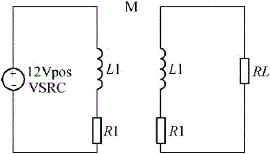
[0015] exist figure 1 Among them, the wireless transmission of electric energy is realized by using the electromagnetic coupling of the primary and secondary coils.

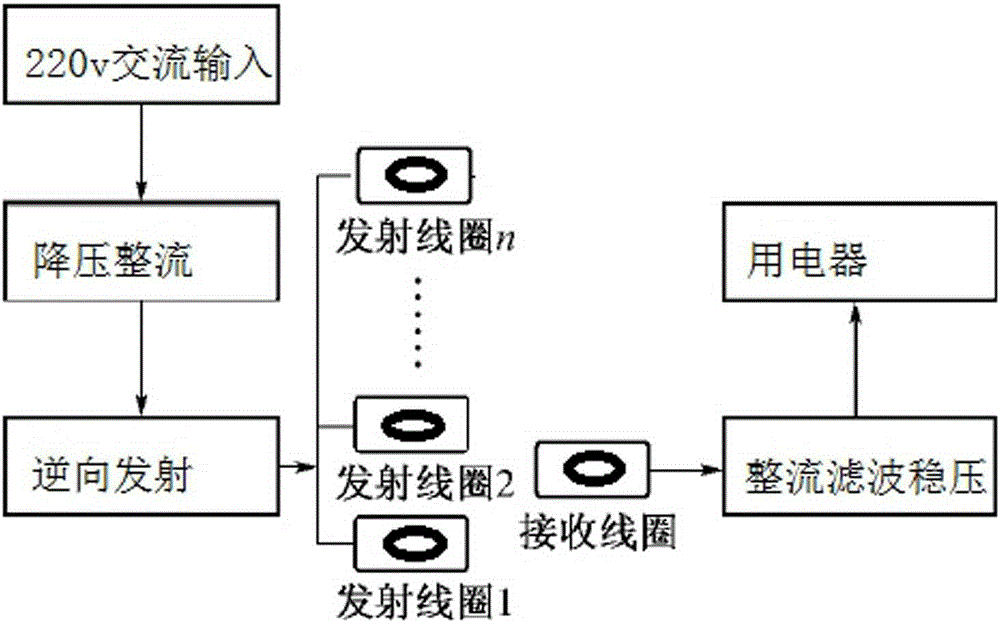
[0016] exist figure 2 In the overall structure of the wireless charger, its power input terminal adopts 220V, 50Hz AC power supply, and is step-down and rectified by a switching power supply to supply power to the transmitting circuit (12V) and the square wave generating circuit (5V) respectively. The electric energy is transmitted through the magnetic field through the transmitting coil, and the receiving end rectifies the received electric energy through the rectifier bridge and outputs it to the consumer in a stabilized voltage. A wireless charger using an H-bridge and a multivibrator includes a transmitting circuit and a receiving circuit.

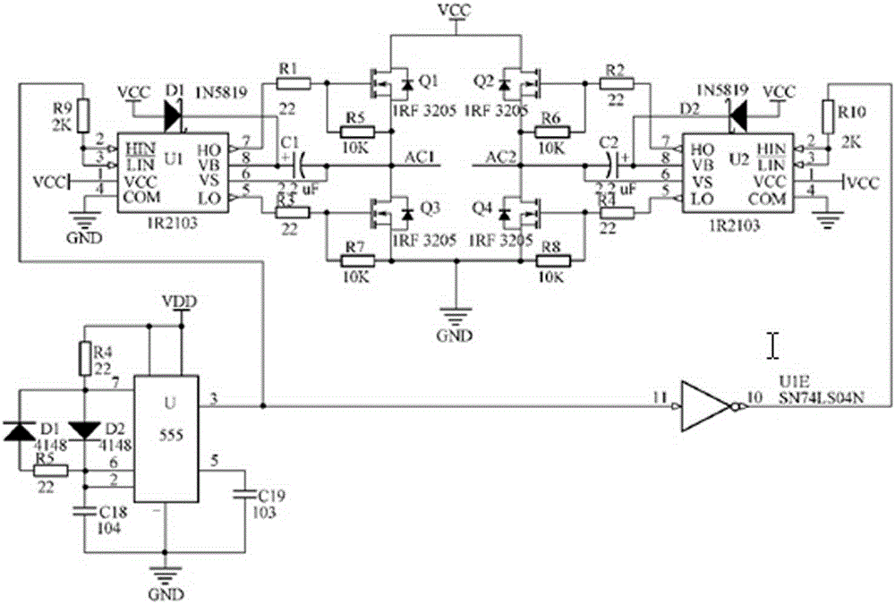
[0017] exist image 3 In the H-bridge circuit, a pair of inverted rectangular waves are required as input drive signals. The NE555 is used to generate a rectangular ...


PUM


Abstract

The invention discloses a wireless charger employing an H bridge and a multivibrator, and the charger consists of a transmitting circuit and a receiving circuit. The charger employs an H bridge inverter and the multivibrator based on NE555, carries out the voltage reduction and rectification of an alternating current through a switching power module, converts a direct current into an alternating current, and transmits the electric energy through a coil. A receiving end carries out the rectification filtering of the received AC electric current, and then carries out the voltage stabilizing, and supplies the power to an electric appliance. The charger is higher in efficiency of electric energy transmission, is safe and reliable, can achieve the simultaneous power supply for a plurality of pieces of mobile equipment in a larger range, and achieves the simultaneous power supply for three pieces of wireless equipment: a cellphone, a keyboard and a mouse.

Description

[0001] Technical field [0002] The present invention relates to a wireless charger using an H-bridge and a multivibrator. Background technique [0003] In recent years, wireless charging technology has become increasingly mature and has become practical with the improvement of charging efficiency. Its main realization schemes include electromagnetic induction type, radio wave radiation type, and electromagnetic resonance type. Electromagnetic induction and radio wave radiation solutions are still in the research and development stage due to their low transmission efficiency and high requirements on the application environment at this stage. At present, the disadvantages of cumbersome manual operation and messy wires for wired charging. Contents of the invention [0004] In order to solve the above problems, the present invention designs a wireless charger using an H-bridge and a multivibrator. [0005] The technical solution adopted by the present invention to solve its ...

Claims


Application Information

Patent Timeline
Patent Type & Authority Applications(China)
IPC IPC(8): H02J50/12H02J7/02
CPCH02J7/025
Inventor 邢筱丹
Owner 邢筱丹
Why Eureka
Try Eureka