A test tube automatic cleaning device

An automatic cleaning and test tube technology, which is applied in the direction of cleaning hollow objects, cleaning methods and utensils, irradiation, etc., can solve the problems of poor cleaning efficiency, low cleaning efficiency, and inability to clean, so as to improve work efficiency, improve accuracy, Labor saving effect

Active Publication Date: 2018-09-14
东营中达石油设备有限公司
View PDF12 Cites 0 Cited by
  • Summary
  • Abstract
  • Description
  • Claims
  • Application Information

AI Technical Summary

Problems solved by technology

[0002] Test tubes are essential equipment in teaching, scientific research or clinical experiments. In the prior art, the cleaning of test tubes is mostly done manually, which has low cleaning efficiency and often cannot be cleaned.
At present, especially for some medical institutions, the amount of test tubes required by the medical laboratory department continues to increase, and most of the test tubes used in this link are made of glass, and some institutions use disposable test tubes, but disposable test tubes exist. Due to the shortcomings of heavy pollution and non-reusable use, most hospitals still use glass test tubes. After the test is completed, the used test tubes need to be cleaned. Cleaning the test tubes is a huge workload.
At present, manual cleaning is mainly used for test tube cleaning, but manual cleaning is time-consuming and laborious, and the cleaning efficiency is low, and it is easy to cause test tube breakage and damage.
[0003] There are also electric devices for cleaning, but the existing electric cleaning devices have problems such as poor cleaning efficiency and low cleaning quality, and after the cleaning of the existing cleaning devices is completed, the water droplets stuck on the test tubes cannot be dried quickly. When taking it, the test tube needs to be dried, which is quite troublesome, and the test tube is not sterilized after cleaning, which cannot effectively ensure the cleanliness and sanitation of the test tube, which may affect the accuracy of subsequent test results

Method used


Image

  • A test tube automatic cleaning device
  • A test tube automatic cleaning device
  • A test tube automatic cleaning device

Examples


Embodiment Construction

[0019] The present invention is realized through the following technical solutions:

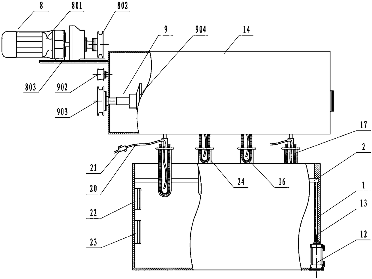
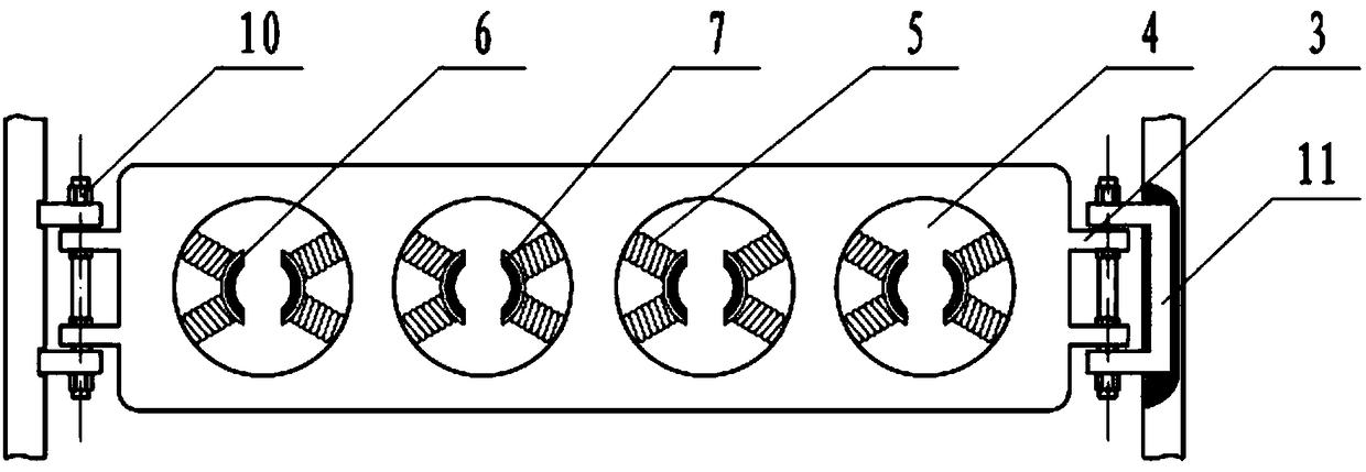
[0020] A test tube automatic cleaning device, including cleaning tank 1, moving plate 2, lifting lug 3, installation hole 4, spring 5, clip 6, rubber pad 7, connecting rod 10, slider I11, jacking cylinder 12, ejector rod 13. Driving device 8, transmission device 9, casing 14, slider II15, push rod 16 and bristles 17, characterized in that: the moving plate 2 is set inside the cleaning tank 1, and the two sides of the moving plate 2 are set There are lugs 3, and the lugs 3 are connected to the slider I11 through the connecting rod 10. The slider I11 is "U" shaped, and the slider I11 is arranged inside the side wall of the cleaning tank 1. The slider I11 The movable plate 2 can be driven to move up and down in the side wall, and a jacking cylinder 12 is arranged below the slider I11, and the ejector rod 13 on the jacking cylinder 12 is connected with the slider I11; A plurality of spaced mount...


PUM


Abstract

Disclosed is an automatic cleaning device for test tubes and belongs to the technical field of automatic cleaning equipment. The automatic cleaning device is characterized in that a top rod on a top lift cylinder is connected with a slider; multiple installation holes are arranged in a moving plate side by side, clamping pieces are arranged in the installation holes, and each clamping piece is connected with the inner edge of each installation hole through a spring; a cabinet is arranged above a cleaning groove, a drive device is fixed on the side face of the cabinet, the drive device is connected with the slide II through a transmission device, the slider is connected with a push bar, bristles are arranged in the push bar, and the push bar is coincided with the axis of the installation holes. The automatic cleaning device has the advantages that the test tubes are cleaned automatically, sterilization and drying functions are added on the basis of the existing technology, and accuracy of detection results is favorably improved.

Description

technical field [0001] The invention relates to an automatic cleaning device for test tubes. Specifically, the device realizes automatic cleaning of test tubes by moving up and down a cylinder and driving a crank connecting rod mechanism through a stepping motor, and belongs to the technical field of automatic cleaning equipment. Background technique [0002] Test tubes are essential equipment in teaching, scientific research or clinical experiments. In the prior art, the cleaning of test tubes is mostly done manually, which has low cleaning efficiency and often cannot be cleaned. At present, especially for some medical institutions, the amount of test tubes required by the medical laboratory department continues to increase, and most of the test tubes used in this link are made of glass, and some institutions use disposable test tubes, but disposable test tubes exist. Due to the shortcomings of heavy pollution and non-reusable use, most hospitals still use glass test tubes....

Claims


Application Information

Patent Timeline
Patent Type & Authority Patents(China)
IPC IPC(8): B08B9/087B08B9/093A61L2/10
CPCA61L2/10B08B9/0808B08B9/0813B08B9/087B08B9/093
Inventor 赵子宁钟建筑
Owner 东营中达石油设备有限公司
Why Eureka
Try Eureka