A hub-ratchet combination structure

A combined structure and ratchet technology, applied in the direction of the hub, clutch, one-way clutch, etc., can solve the problems of offsetting consumption of motion performance, elongated distance, wear of ratchet block 73 and tooth groove 611, etc., and achieves both safety and improvement The effect of certainty

Inactive Publication Date: 2017-06-27
CHOSEN
View PDF6 Cites 2 Cited by
  • Summary
  • Abstract
  • Description
  • Claims
  • Application Information

AI Technical Summary

Problems solved by technology

[0003] It is not difficult to find that there are still some deficiencies in the above-mentioned conventional structure in detail, and the main reasons are as follows: in the above-mentioned conventional hub structure, the engagement between the tooth groove 611 in the hub seat 60 and the ratchet block 73 groups is radial Although it can effectively provide the smooth operation of the wheel hub on the bicycle, under long-term riding, the force on the ratchet block 73 cannot be evenly distributed to all the ratchet blocks when the ratchet block 73 jumps teeth relative to the tooth groove 611 73, and the ends of some ratchet blocks 73 are subjected to relatively concentrated friction force, which easily causes accelerated wear of the ratchet block 73 and the tooth groove 611, and further causes the ratchet block 73 to have a tooth detachment. In addition, it also causes the need to replace the ratchet block frequently, resulting in an increase in cost
[0004] In addition, the number of tooth grooves 611 inside the ratchet groove 61 is small, causing the distance between each tooth groove 611 to be elongated, and the angle of engagement between the ratchet block 73 and the tooth grooves 611 is also greater than 90 degrees, which also increases the number of ratchet teeth. The stroke of engagement between the block 73 and the tooth groove 611 makes the frictional resistance between the ratchet block 73 and the tooth groove 611 relatively large, causing the movement efficiency to be offset and consumed, thereby reducing the number of rotations of the hub and the sliding distance of the bicycle. When the rider pedals again, the distance between the tooth grooves 611 may be elongated, so that the ratchets 73 cannot be immediately provided to reach the state of meshing and interlocking, and there is a doubt that the pedal will be empty, which is really lacking in riding safety.

Method used


Image

  • A hub-ratchet combination structure
  • A hub-ratchet combination structure
  • A hub-ratchet combination structure

Examples


Embodiment Construction

[0052] The present invention will be further described below with reference to the accompanying drawings and specific embodiments, so that those skilled in the art can better understand and implement the present invention, but the examples cited are not intended to limit the present invention.

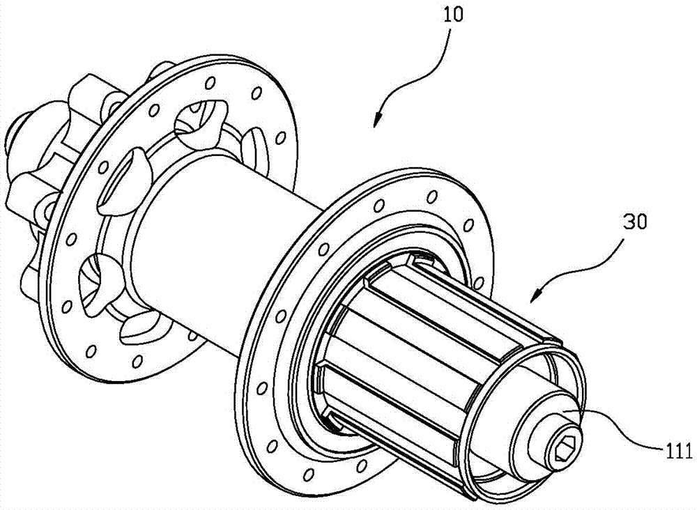
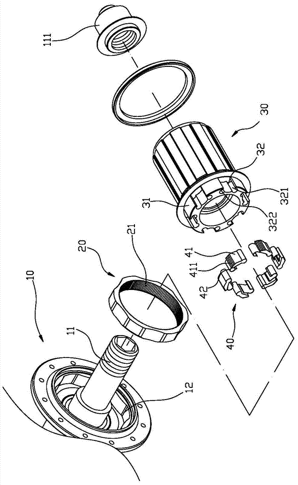
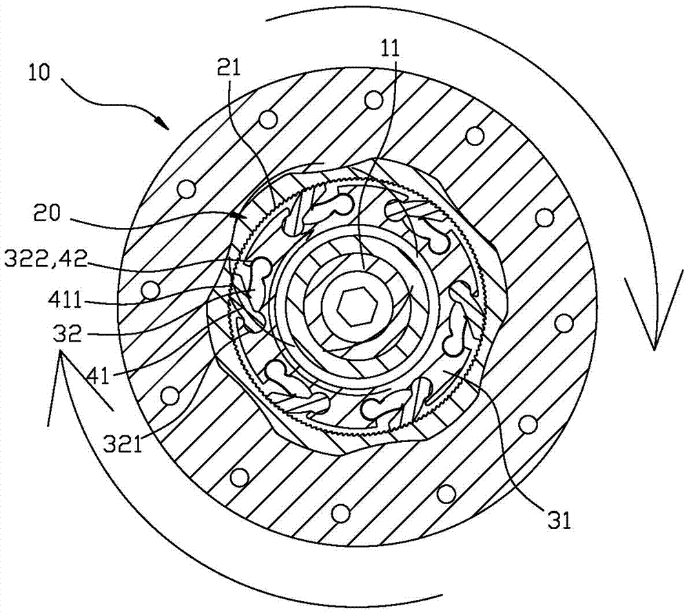
[0053] First, see figure 1 , 2 Cooperate image 3 , 4 , 5, which includes: a hub seat 10, a linkage ring 20, a sleeve seat 30 and a ratchet tooth set 40, wherein a hub seat 10 penetrates a shaft 11, and can be The shaft 11 is rotated and actuated, and a non-circular hole-shaped combined chamber 12 is provided on one side of the hub seat 10 to provide a connecting ring 20 for embedding and fixing. The outer circumference of the connecting ring 20 is non-circular, and the inner A number of linkage teeth 21 are arranged in sequence, and the number of linkage teeth 21 of the linkage ring 20 is between 145 teeth and 155 teeth. The optimal number of teeth is 150 teeth. The angle of 21 is betwe...


PUM


Abstract

The invention provides a hub-ratchet combination structure comprising a hub base, a linkage ring, a sleeve base and a ratchet tooth group. Linkage teeth of the linkage ring are characterized by a great tooth number and a small pitch, and the number of the teeth can reach up to 155 at most. Each pawl member of the ratchet tooth group is provided with meshing teeth with a small pitch corresponding to the linkage teeth. The sliding distance of the meshing teeth on the tooth ends of the linkage teeth can be effectively reduced and further the spacing distance of meshing linkage of the ratchet tooth group and the linkage ring can be shortened, so that the state of meshing linkage can be reached quickly, the pedaling gaps can be reduced, the definiteness of riding and pedaling can be improved greatly and the safety is improved.

Description

Technical field [0001] The invention relates to a hub unit, in particular to a hub ratchet combined structure. Background technique [0002] Press, there is a hub ratchet device that can quickly engage, please refer to Picture 9 As shown, it includes a spindle 50, a hub seat 60, which is rotatably sleeved on the spindle 50, and a ratchet groove 61 is recessed at one end, and a plurality of ratchet grooves 61 are formed at equal intervals on the inner peripheral surface of the ratchet groove 61 A tooth groove 611, a ratchet cylinder 70, which rotatably sleeves the spindle 50, the ratchet cylinder 70 is provided with a wheel-shaped body 71 inserted into the ratchet groove 61 at one end facing the hub seat 60, the wheel The shape body 71 is provided with a plurality of block grooves 72 that can be equally divided into two groups and alternately arranged with each other. The distance between each block groove 72 and the adjacent two sides is designed to be arranged at different inter...

Claims


Application Information

Patent Timeline
Patent Type & Authority Applications(China)
IPC IPC(8): F16D41/30B60B27/00
CPCB60B27/00F16D41/30
Inventor 陈青树
Owner CHOSEN
Why Eureka
Try Eureka